Improved method and device for high water pressure difference gate sealing

A technology of high water pressure difference and water stop device, applied in water conservancy projects, marine engineering, coastline protection and other directions, can solve problems such as water leakage, reduce wear, enhance water stop effect, and reduce friction.

Active Publication Date: 2016-09-21
CHINA POWER CONSRTUCTION GRP GUIYANG SURVEY & DESIGN INST CO LTD
View PDF6 Cites 3 Cited by
  • Summary
  • Abstract
  • Description
  • Claims
  • Application Information

AI Technical Summary

Problems solved by technology

[0004] The object of the present invention is to provide an improved method and device for water sealing of high water pressure differential gates, so as to solve the problems caused by the water seal head and water pressure on both sides of the gate. The technical problem of water leakage due to the lack of tight contact of the sealing plate, thereby overcoming the deficiencies of the existing technology

Method used


Image

  • Improved method and device for high water pressure difference gate sealing
  • Improved method and device for high water pressure difference gate sealing
  • Improved method and device for high water pressure difference gate sealing

Examples


Embodiment 1

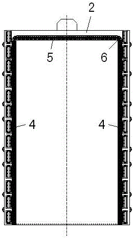
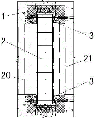
[0025] in the gate slot 1 gate 2 . at the gate 2 The downstream side is symmetrically equipped with a door-shaped water stop device 3 , in the door slot 1 Upper setting and water stop device 3 The position of the water seal head corresponds to the water seal seat plate 16 . Water stop device 3 Asymmetrical concave water seal support seat 7 , water seal 8 , inner pressure plate 9 and outer pressure plate 10 composition. Asymmetric concave water seal support seat 7 Fastened to the gate by welding 2 on, the rest of the components are bolted through the 11 And asymmetrical concave water seal support seat 7 fixed on the gate 2 superior. water seal 8 water inlet hole for the side 15 The round head "mountain" type water seal, its internal setting U Cavity 14 , inlet hole 15 Approximate equidistant setting, water inlet holes 15 and downstream water bodies 21 connected, water inlet 15 and U Cavity 14 Connected; the water seal mate...

Embodiment 2

[0027] in the gate slot 1 gate 2 . at the gate 2 The downstream side is symmetrically equipped with a door-shaped water stop device 3 , in the door slot 1 Upper setting and water stop device 3 The position of the water seal head corresponds to the water seal seat plate 16 . Water stop device 3 Asymmetrical concave water seal support seat 7 , water seal 8 , inner pressure plate 9 and outer pressure plate 10 composition. Asymmetric concave water seal support seat 7 Fastened to the gate by welding 2 on, the rest of the components are bolted through the 11 And asymmetrical concave water seal support seat 7 fixed on the gate 2 superior. water seal 8 water inlet hole for the side 15 The round head "mountain" type water seal, its internal setting U Cavity 14 , inlet hole 15 Approximate equidistant setting, water inlet holes 15 with upstream water body 20 connected, water inlet 15 and U Cavity 14 Connected; the water seal materia...


PUM


Abstract

The invention discloses an improved method and a device for high water pressure difference gate sealing. The improved method and the device are characterized in that the section of a water seal is in a blunt-nosed epsilon shape and is of a dual-layer structure; one protruded surface of the water seal is a soft rubber layer, and the other surface of the water seal is a hard rubber layer; a U-shaped cavity is formed in an interface between the soft rubber layer and the hard rubber layer; a water inlet hole is formed in one side of the U-shaped cavity and communicates with an upstream water body or a downstream water body; by means of the upstream water body or the downstream water body entering the U-shaped cavity, the soft rubber layer of the water seal generates expansive deformation deflecting towards the downstream direction, a round head of the water seal is enabled to tightly extrude the surface of a water seal sitting board, thereby improving the sealing effect of the water seal; and for preventing excessive deformation of the head of the water seal, a warping boss is arranged at a position, close to the head of the water seal, of a water seal inner pressing plate, and the condition of water leakage due to creepage of a water seal head caused by excessive deformation of the head of the water seal is limited. According to the improved method and the device disclosed by the invention, the technical problem of water leakage due to unclosed contact between the water seal head and the water seal sitting board in a two-side stressed state of a gate is well solved.

Description

technical field [0001] The invention relates to an improved method and device for water-stopping of a gate with high water pressure difference, belonging to the technical field of metal structures of water conservancy and hydropower projects. Background technique [0002] For the gate, it is generally in a state of single-sided compression, and for some ultra-high dams with a height of about 300m, based on safety requirements, the reservoir needs to be lowered to below 200m, which exceeds the range of 160m that the current single-stage gate can withstand. Therefore, some projects The method of setting multi-stage gates on the same floor of the emptying system is adopted to solve the problem that the gates cannot bear too high water head. The water load borne by the gate is adjusted from the state of one-sided compression to the state of double-sided compression, which reduces the water load borne by the gate. [0003] Through the above method, the water load borne by the ga...

Claims


Application Information

Patent Timeline
Patent Type & Authority Applications(China)
IPC IPC(8): E02B7/54
CPCE02B7/54
Inventor 王兴恩
Owner CHINA POWER CONSRTUCTION GRP GUIYANG SURVEY & DESIGN INST CO LTD
Why Eureka
Try Eureka