Oil shale in situ heat injection exploitation drilling well cementation method

An oil shale and well cementing technology, which is applied in the cementing of oil shale in-situ thermal injection drilling, oil sand thermal injection production, and heavy oil fields, and can solve oil stringing accidents, steam stringing, cementing casing, Problems such as deformation and damage of the cement sheath, to achieve the effects of preventing steam passing, high cementing strength, and improving cementing quality

Inactive Publication Date: 2016-09-21
TAIYUAN UNIV OF TECH
View PDF4 Cites 0 Cited by
  • Summary
  • Abstract
  • Description
  • Claims
  • Application Information

AI Technical Summary

Problems solved by technology

[0004] The purpose of the present invention is to overcome the shortcomings of the prior art, to provide a cementing method for oil shale in-situ thermal injection drilling, and to solve the problem that the cementing method of the prior art can easily lead to cementing casing, cement The ring is deformed and damaged, causing technical problems of steam and oil accidents

Method used


Image

  • Oil shale in situ heat injection exploitation drilling well cementation method
  • Oil shale in situ heat injection exploitation drilling well cementation method
  • Oil shale in situ heat injection exploitation drilling well cementation method

Examples


Embodiment 1

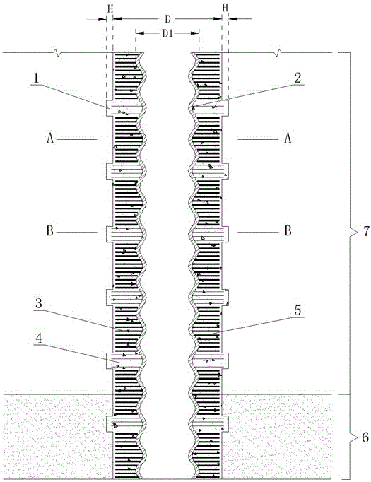
[0023] Such as figure 1 , 2 , Shown in 3, a kind of concrete steps of the well cementing method of oil shale in-situ thermal injection exploitation drilling:

[0024] 1. Drilling in the target in-situ heat injection area of ​​the selected oil shale 6 to form a borehole with an inner diameter of D=450 mm, and then space a certain length in the borehole to expand the diameter of the drill hole in the formation to form a ring groove 1. The ring The depth of groove 1 H=30mm;

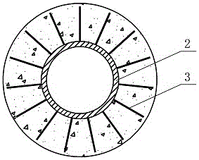
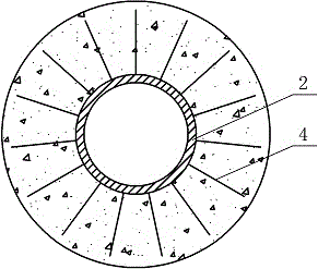
[0025] 2. Select diameter D 1 = 300mm metal bellows is the cementing casing 2, and steel bars 3 and steel wires 4 are evenly welded radially outside the cementing casing 2, and the position of the steel wire 4 corresponds to the position of the ring groove 1;

[0026] 3. Press the cementing casing 2 that has been welded with the steel bar 3 and the steel wire 4 into the borehole, and the depth that the steel wire 4 penetrates into the ring groove 1 is 5 mm;

[0027] 4. Use high-temperature resistant ceme...

Embodiment 2

[0032] Such as figure 1 , 2 , Shown in 3, a kind of concrete steps of the well cementing method of oil shale in-situ thermal injection exploitation drilling:

[0033] 1. Drilling in the target in-situ heat injection area of ​​the selected oil shale 6 to form a borehole with an inner diameter of D=650 mm, and then space a certain length in the borehole to expand the diameter of the drill hole in the formation to form a ring groove 1. The ring The depth of groove 1 H=100mm;

[0034] 2. Select diameter D 1 = 450mm metal bellows is the cementing casing 2, and steel bars 3 and steel wires 4 are evenly welded radially outside the cementing casing 2, and the position of the steel wire 4 corresponds to the position of the ring groove 1;

[0035] 3. Press the cementing casing 2 that has been welded with the steel bar 3 and the steel wire 4 into the borehole, and the depth of the steel wire 4 penetrating into the ring groove 1 is 30mm;

[0036] 4. Use high-temperature resistant ceme...

Embodiment 3

[0041] Such as figure 1 , 2 , Shown in 3, a kind of concrete steps of the well cementing method of oil shale in-situ thermal injection exploitation drilling:

[0042] 1. Drilling in the target in-situ heat injection area of ​​the selected oil shale 6 to form a borehole with an inner diameter of D=550 mm, and then space a certain length in the borehole to expand the diameter of the drill hole in the formation to form a ring groove 1. The ring The depth of groove 1 H=60mm;

[0043] 2. Select diameter D 1 The metal bellows of =350mm is the cementing casing 2, and steel bars 3 and steel wires 4 are evenly welded radially outside the cementing casing 2, and the position of the steel wire 4 corresponds to the position of the ring groove 1;

[0044] 3. Press the cementing casing 2 that has been welded with the steel bar 3 and steel wire 4 into the borehole, and the depth that the steel wire 4 penetrates into the ring groove 1 is 15mm;

[0045] 4. Use high-temperature resistant ce...


PUM


Abstract

An oil shale in situ heat injection exploitation drilling well cementation method relates to the oil gas heat injection exploitation technology, and solves the technical problems that the existing technology can easily cause deformations and damages on a cementation sleeve and a cement ring under high temperature environment, and thus causing gas intermingling and oil intermingling problems; the method comprises the following steps: drilling on a selected oil shale object in situ heat injection zone so as to form a borehole, and expanding the borehole diameter at intervals in the borehole so as to form a loop groove; selecting a metal bellows as the well cementation sleeve, and welding steel bars and steel wires at intervals in a radial direction outside the well cementation sleeve; pressing the well cementation sleeve with welded steel bars and steel wires into the borehole; using high temperature resistance cement to grout the gap between the well cementation sleeve and the borehole, the high temperature resistance cement mortar mixes into the steel bars and steel wires and consolidate to form a cement ring, and the cement ring and the stratum form a tooth-shaped occlusion structure. The method is applied to oil shale in situ heat injection oil gas exploitation; the cementation intensity between the well cementation sleeve, the cement ring and the stratum are high, and the well cementation quality is good, thus effectively preventing gas intermingling and oil intermingling problems.

Description

technical field [0001] The invention belongs to the technical field of oil and gas in-situ thermal injection exploitation of oil shale, specifically relates to a cementing method for in-situ thermal injection exploitation of oil shale, and is especially suitable for in-situ thermal injection extraction of oil and gas in oil shale, and is also suitable for thick Thermal injection mining of oil and oil sands. Background technique [0002] At present, in the process of thermal recovery of heavy oil, cementing is an important technical link. In the "casing-cement sheath-formation" combination, the casing and cement sheath are often deformed and damaged due to uneven thermal expansion. In particular, separation layers are more likely to occur between the casing and the cement sheath, and between the cement sheath and the formation contact surface, which cannot be integrated, resulting in accidents of steam and oil on site. The main solution in the prior art is to add different k...

Claims


Application Information

Patent Timeline
Patent Type & Authority Applications(China)
IPC IPC(8): E21B33/13E21B33/14E21B7/20E21B7/28
CPCE21B33/13E21B7/20E21B7/28E21B33/14
Inventor 康志勤赵阳升杨栋梁卫国赵静耿毅德
Owner TAIYUAN UNIV OF TECH
Why Eureka
Try Eureka