Air cooling hydraulic station with secondary heat dissipating pipeline

A technology for secondary heat dissipation and hydraulic station, applied in the field of air-cooled hydraulic station, can solve the problem that the effect of the heat dissipation method of a separate fan needs to be improved, and achieve the effect of good secondary heat dissipation, good heat dissipation effect, and reduced traveling speed.

Active Publication Date: 2016-09-21
TIANJIN URANUS HYDRAULIC MACHINERY
View PDF7 Cites 3 Cited by
  • Summary
  • Abstract
  • Description
  • Claims
  • Application Information

AI Technical Summary

Problems solved by technology

In actual use, it is found that since the radiator is located above the fuel tank, the cold air sucked by the outside fan performs heat exchange with the radiator, and the hot air is blo

Method used


Image

  • Air cooling hydraulic station with secondary heat dissipating pipeline
  • Air cooling hydraulic station with secondary heat dissipating pipeline

Examples


Example Embodiment

[0014] The present invention will be further described below with reference to the examples. The following examples are illustrative, not restrictive, and the protection scope of the present invention cannot be limited by the following examples.

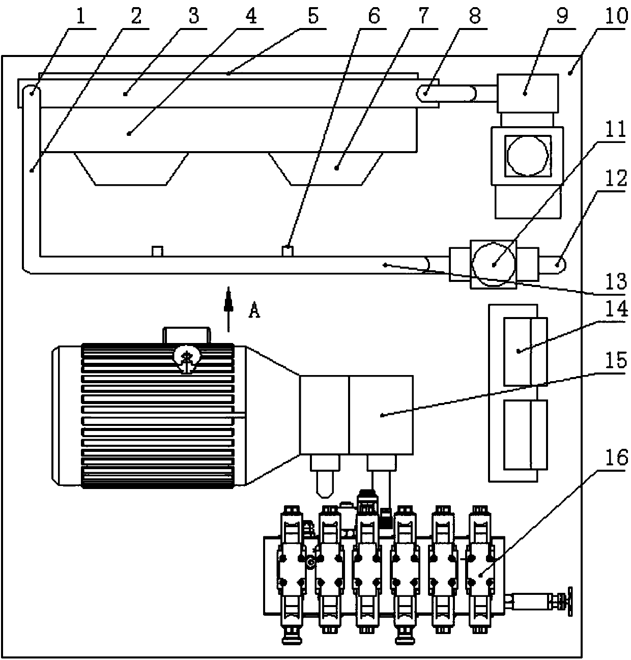
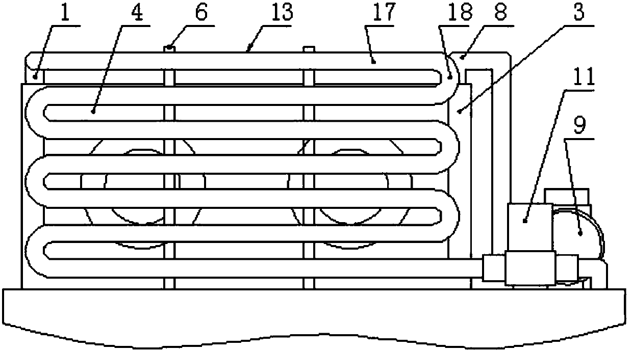
[0015] An air-cooled hydraulic station with a secondary heat dissipation pipeline, such as figure 1 , 2 As shown, the present invention includes a fuel tank 10, an oil supply power source 15, a switch valve group 16, a radiator 3 and a fan casing 4. The innovation of the present invention is that the switch valve group is installed at the front end of the upper end face of the fuel tank, and the switch valve group The oil supply power source is installed on the upper end face of the rear fuel tank, and the fan casing is installed at the rear end of the upper end face of the fuel tank. At least one fan 7 is installed, and a secondary heat dissipation pipeline 13 with multiple bends in the vertical direction is arranged on the upper e...


PUM


Abstract

The invention relates to an air cooling hydraulic station with a secondary heat dissipating pipeline. A switch valve group is arranged at the front end of the upper end face of an oil tank; an oil supply power source is arranged on the upper end face of the oil tank at the rear part of the switch valve group; a fan casing is arranged at the rear end of the upper end face of the oil tank; a heat dissipater is arranged at the outer side, facing the oil tank, of the fan casing; at least one fan is arranged at the inner side, facing the oil tank, of the fan casing; and the secondary heat dissipating pipeline with multiple bends in the vertical direction is arranged on the upper end face of the oil tank between the oil supply power source and the fan casing. According to the air cooling hydraulic station disclosed by the invention, the fans suck cold air from the upper end face direction of the oil tank, and then the cold air is blown out by the outward heat dissipater, so that the heat of other hydraulic components on the upper end face of the oil tank can be taken way when air flows; the secondary heat dissipating pipeline can be produced into a thicker pipeline or can be arranged into multiple layers, so that the advancing speed of oil is reduced, and a secondary heat dissipating effect is better.

Description

technical field [0001] The invention belongs to the technical field of improving the oil heat dissipation structure of a hydraulic station, in particular to an air-cooled hydraulic station with a secondary heat dissipation pipeline. Background technique [0002] The hydraulic station is the core of the hydraulic system. It transmits the oil to different hydraulic cylinders through the oil supply power source and the switch valve group to realize different actions to complete functions such as pushing and lifting. Since the oil will generate heat when it works again, especially in the hydraulic system with frequent movements or high pressure, the temperature of the oil will heat up greatly. If the temperature cannot be lowered, it will inevitably affect the stability of the oil. The existing air-cooled The structure of the type heat dissipation method includes: a fan casing 4, a radiator 3 and a circulating power source 9, all of which are installed on the upper surface of th...

Claims


Application Information

Patent Timeline
IPC IPC(8): F15B21/04
CPCF15B21/042
Inventor 李培元王超光刘兵于安才赵斌
Owner TIANJIN URANUS HYDRAULIC MACHINERY
Why Eureka
Try Eureka