A hydraulic/pneumatic high pressure relief valve

A pneumatic high-pressure, pressure relief valve technology, applied in the field of pressure relief valves, can solve problems such as danger, abnormal equipment operation, pipeline leakage, etc., and achieve the effect of light weight, small size and high reliability

Active Publication Date: 2018-02-16
XIAN AEROSPACE PROPULSION TECH INST
View PDF5 Cites 0 Cited by
  • Summary
  • Abstract
  • Description
  • Claims
  • Application Information

AI Technical Summary

Problems solved by technology

The commonly used safety valve is the overflow valve, which can only limit the maximum pressure of the liquid pipeline to a certain value, and cannot directly relieve the pressure to zero.
Due to the high oil pressure in pressure vessels and pipelines in the working environment, sometimes reaching above 60MPa, accidents such as pipeline leakage and abnormal operation of equipment are prone to occur. It is easy to cause casualties of personnel and equipment, extremely dangerous, and has potential safety hazards

Method used


Image

  • A hydraulic/pneumatic high pressure relief valve
  • A hydraulic/pneumatic high pressure relief valve
  • A hydraulic/pneumatic high pressure relief valve

Examples


Embodiment Construction

[0017] The present invention will be further described in detail below in conjunction with the accompanying drawings and embodiments.

[0018] This embodiment provides a hydraulic high-pressure pressure relief valve, which can adapt to 60MPa high-pressure oil, is small in size, light in weight, good in safety and high in reliability, and can realize remote pressure relief.

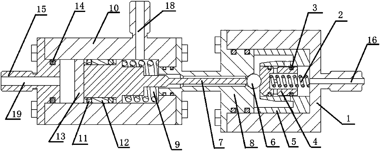
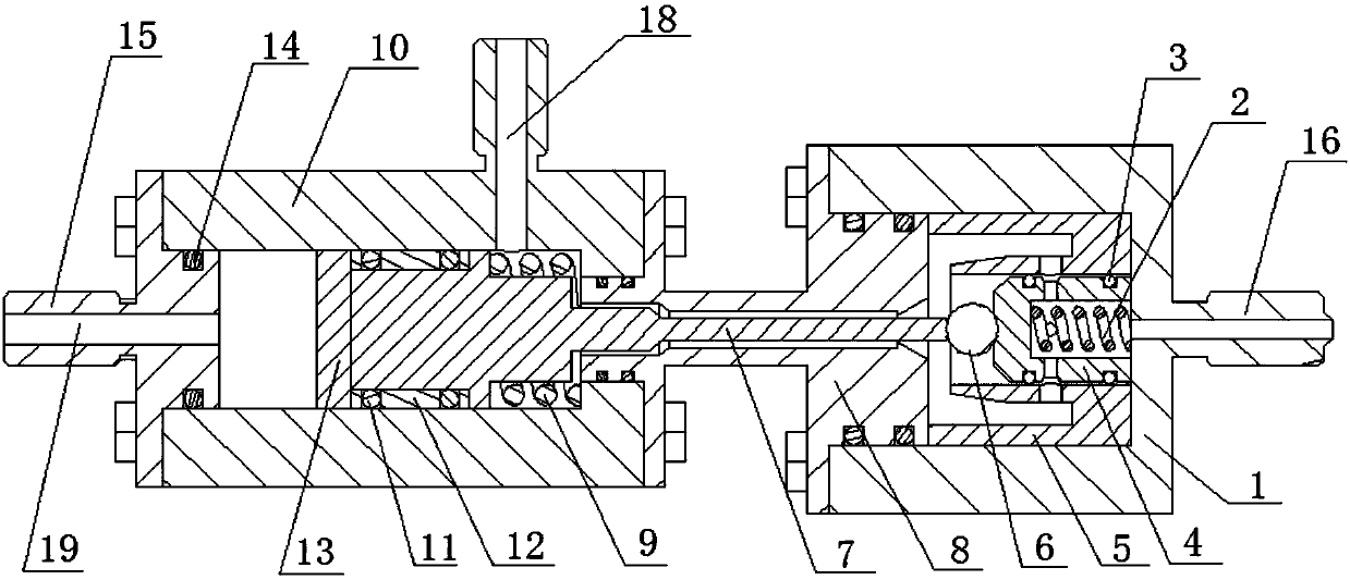
[0019] Such as figure 1 and figure 2 As shown, the high pressure relief valve has three ports connected to the outside, which are high pressure oil port 16 , low pressure oil port 19 and oil return port 18 .

[0020] Its overall structure includes a hyperbaric chamber, a low pressure chamber and a connecting flange 8, wherein the hyperbaric chamber includes: a hyperbaric chamber shell 1 and a hyperbaric chamber spring 2 located inside the hyperbaric chamber shell 1, a cylindrical valve core 4 and a throttle chamber 5 . The hyperbaric chamber shell 1 is a structure with one end open and one end closed, ...


PUM


Abstract

The invention discloses a hydraulic / pneumatic high pressure relief valve. The pressure relief valve can utilize low-pressure oil / gas as power and adapt to high-pressure oil unloading and is small in size, light and high in reliability, and remote pressure relief can be achieved. The hydraulic / pneumatic high pressure relief valve overall structurally comprises a high-pressure bin, a low-pressure bin and a connecting flange used for connecting the high-pressure bin and the low-pressure bin. According to the pressure relief valve, the manner of combining a columnar valve and a ball valve is adopted, so that sealing of high-temperature and high-pressure oil is guaranteed. When pressure relief is needed, low-pressure oil (gas) input by the low-pressure bin is utilized, a needle-shaped ejector rod is pushed to open a sealing ball and a columnar valve element of the high-pressure bin, and pressure relief is completed. To avoid vibration and noise and prevent a sealing component from being eroded, a special changing throttling bin clearance channel is designed, and therefore the pressure of flowing high-pressure oil is reduced through water head losing. After pressure relief, the oil flows along with the clearance and flows out of a pressure relief valve oil return connector.

Description

technical field [0001] The invention relates to a pressure relief valve, in particular to a pressure relief valve used for high-pressure containers / oil pipelines in high-temperature and high-pressure dangerous situations. Background technique [0002] In construction machinery equipment and special pressure test occasions such as oil fields, construction, and metallurgy, there are fluid transmission systems such as high-temperature and high-pressure liquid containers / oil pipelines. The commonly used safety valve is the overflow valve, which can only limit the maximum pressure of the liquid pipeline to a certain value, but cannot directly relieve the pressure to zero. Due to the high oil pressure in pressure vessels and pipelines in the working environment, sometimes reaching above 60MPa, accidents such as pipeline leakage and abnormal operation of equipment are prone to occur. It is easy to cause casualties of personnel and equipment, which is extremely dangerous and has po...

Claims


Application Information

Patent Timeline
Patent Type & Authority Patents(China)
IPC IPC(8): F16K17/10F16K27/08
CPCF16K17/0406F16K17/044F16K17/046F16K17/10F16K27/08
Inventor 赵宪斌侯晓张乐赵汉青
Owner XIAN AEROSPACE PROPULSION TECH INST
Why Eureka
Try Eureka