Package structure and manufacturing method thereof

A technology of packaging structure and manufacturing method, which is applied to electrical components, impedance networks, etc., can solve the problems of poor packaging structure stability, device failure, and large volume of the acoustic wave reflection layer, so as to simplify the packaging process, reduce packaging costs, and reduce volume. Effect

Active Publication Date: 2016-09-21
RDA MICROELECTRONICS SHANGHAICO LTD
View PDF8 Cites 8 Cited by
  • Summary
  • Abstract
  • Description
  • Claims
  • Application Information

AI Technical Summary

Problems solved by technology

One is that the stability of the packaging structure that realizes the acoustic wave reflection layer is poor, and the airtightness of the packaging structure is easily damaged in some harsh environments, which

Method used


Image

  • Package structure and manufacturing method thereof
  • Package structure and manufacturing method thereof
  • Package structure and manufacturing method thereof

Examples


Embodiment Construction

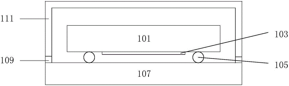
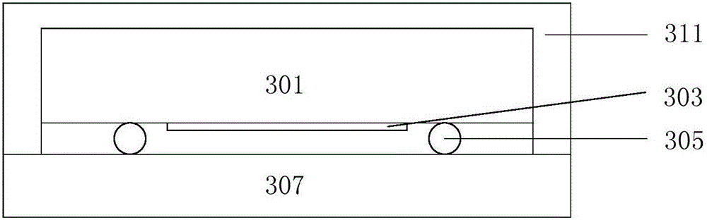
[0033] see Figure 3a , which is the first embodiment of the packaging structure of the present application. The substrate 301 with the device 303 is flip-chip soldered on the substrate 307 , and the metal bump 305 is used to electrically lead the pins of the device 303 to the substrate 307 . The substrate is, for example, a semiconductor substrate such as silicon, or a piezoelectric crystal substrate such as lithium tantalate or lithium niobate. The device 303 is, for example, a surface acoustic wave device or a bulk acoustic wave device. The metal bump 305 is, for example, made of gold, tin, silver, copper or alloys thereof. The substrate 307 is, for example, a resin substrate for packaging. The first encapsulation layer 311 tightly wraps the substrate 301 , and combines with the substrate 307 to form a sealing structure surrounding the substrate 301 and the device 303 . The sealing structure has a cavity in it. The first encapsulation layer 311 may be a single-layer fi...


PUM


Abstract

The invention discloses a package structure. According to the invention, a substrate provided with a device is welded on a base plate in an inverted manner, and pins of the device are electrically led outward to the base plate by metal convex blocks. The package structure is characterized in that the substrate is tightly wrapped by a first package layer, the first package layer is combined with the base plate so as to form a sealed structure which surrounds the substrate and the device, and the sealed structure is internally provided with a cavity; and the first package layer is a multilayer film. The air tightness and the stability of the package structure are considered, and the volume of the package structure is reduced as far as possible at the same time. In addition, the packaging process is simplified, and the packaging cost is reduced.

Description

technical field [0001] The present application relates to a packaging structure for airtight protection of a surface acoustic wave device or a bulk acoustic wave device. Background technique [0002] The radio frequency filter is an important component of the radio frequency front end (RF front end) circuit. It is used on the receiving channel to filter the spurious signal input by the antenna, and transmits the required signal to the post-stage power amplifier; it is used on the transmitting channel to filter The signal output by the power amplifier, and the required signal is transmitted to the transmitting port and transmitted externally through the antenna. [0003] The radio frequency filter mainly includes a surface acoustic wave (abbreviated as SAW) filter, a bulk acoustic wave (abbreviated as BAW) filter, a dielectric filter (dielectric filter) and the like. Due to the large size of the dielectric filter, the radio frequency filters currently used in mobile communic...

Claims


Application Information

Patent Timeline
IPC IPC(8): H03H9/25H03H3/08
CPCH03H3/08H03H9/25
Inventor 祝明国李平孙成龙彭彦豪宋博胡念楚贾斌
Owner RDA MICROELECTRONICS SHANGHAICO LTD
Why Eureka
Try Eureka