Dual-waveguide/multi-waveguide channel structure and tr module working in w-band
A channel structure, dual-waveguide technology, applied in waveguides, waveguide-type devices, radio wave measurement systems, etc., can solve the problems of difficult waveguide structure, complex internal structure, and difficulty, so as to solve the problem of air tightness and avoid mutual interference. , taking into account the effect of air tightness
- Summary
- Abstract
- Description
- Claims
- Application Information
AI Technical Summary
Problems solved by technology
Method used
Image
Examples
Embodiment 2
[0041] This embodiment discloses a multi-waveguide channel structure working in the W band.
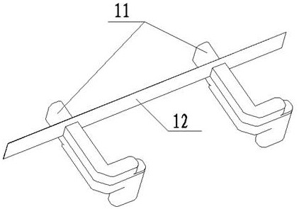
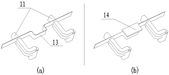
[0042] As mentioned above, the multi-waveguide channel structure can be extended on the basis of the above-mentioned dual-waveguide channel structure. like Figure 6 Shown is a schematic diagram of the structure expanded to four channels, and expanded to more channels, it can be expanded in the same way. For the multi-waveguide channel structure, preferably, the shapes surrounded by the raised structures 13 between adjacent output waveguide channels 11 are all the same, for example, they are all rectangular. Of course, the shapes surrounded by the raised structures 13 are not excluded. In different cases, or even if the enclosing shapes are the same, they are not necessarily limited to rectangles. Moreover, the protruding directions of the protruding structures are the same, so as to facilitate industrial mass production and processing. Similarly, it does not mean that the predeterm...
Embodiment 3
[0044] like Figure 7 As shown, it is the circuit structure diagram of a hermetically sealed multi-waveguide channel TR module working in the W-band. The 1-to-2 power splitter is divided into two channels, which are respectively input into two driver TR chips, and then connected to the 1-to-4 power splitter to divide into 4 channels, and the two 1-to-4 power splitters have a total of 8 outputs. Each signal is input to the vector modulation chip, and the signal is phase-shifted and attenuated in the vector modulation chip. The output of the vector modulation chip is connected to the final stage TR chip for amplification, and the amplified signal is sent to the final stage power amplifier chip for power amplification; finally, after power The amplified signal is sent to the circulator, and then connected to the output waveguide channel (that is, the output waveguide interface). For the millimeter-wave receiving signal, the path is opposite to that of the transmitting signal, bu...
PUM
 Abstract
Description
Claims
Application Information
 - R&D
- Intellectual Property
- Life Sciences
- Materials
- Tech Scout
- Unparalleled Data Quality
- Higher Quality Content
- 60% Fewer Hallucinations
Browse by: Latest US Patents, China's latest patents, Technical Efficacy Thesaurus, Application Domain, Technology Topic, Popular Technical Reports.
© 2025 PatSnap. All rights reserved.Legal|Privacy policy|Modern Slavery Act Transparency Statement|Sitemap|About US| Contact US: help@patsnap.com


