Manufacturing method of personalized retaining splint for department of orthopedics

A manufacturing method and splint technology, applied in fractures, medical science, etc., can solve problems such as inability to meet the force requirements of affected limbs, discomfort for patients to wear, and rough hollowed out structure, so as to prevent insufficient connection strength or inconvenient connection, and make it comfortable to wear , to ensure the effect of portability

Active Publication Date: 2016-09-28
NANJING UNIV OF AERONAUTICS & ASTRONAUTICS
View PDF2 Cites 11 Cited by
  • Summary
  • Abstract
  • Description
  • Claims
  • Application Information

AI Technical Summary

Problems solved by technology

[0005] Although the existing personalized external fixation splints have been able to achieve digital manufacturing, many technologies are still incomplete
First, the air hole construction technology of the model in the prior art cannot meet the force requirements of the affected limb, resulting in discomfort for the patient to wear and easy to cause secondary displacement; second, the hollow structure of the prior art is often very rough and the transition is uneven , which is not beautiful and is easy to scratch the skin and affect blood circulation; third, the existing technology does not combine the model bias algorithm to make the retention of the splint reach the optimal position

Method used


Image

  • Manufacturing method of personalized retaining splint for department of orthopedics
  • Manufacturing method of personalized retaining splint for department of orthopedics
  • Manufacturing method of personalized retaining splint for department of orthopedics

Examples


Embodiment

[0040] The manufacturing method of the personalized orthopedic retention splint of the present embodiment comprises the following steps:

[0041] 1) Scan the patient's fracture (taking the wrist as an example) to obtain the limb surface of the patient's fracture.

[0042] In this embodiment, when the fracture is scanned, the two-dimensional image data obtained by CT scanning is used for three-dimensional model reconstruction combined with the original three-dimensional model directly obtained by the optical scanner, and then the surface of the three-dimensional model is obtained, that is, the limb surface of the patient's fracture. Of course, it is also possible to directly use 3D non-contact scanning, or use 2D images such as CT for 3D reconstruction to obtain the original 3D model.

[0043] The data obtained by CT can help to use medical theory to better analyze the affected limb, but the accuracy of its curved surface shape is low, and the data obtained by the optical scann...


PUM


Abstract

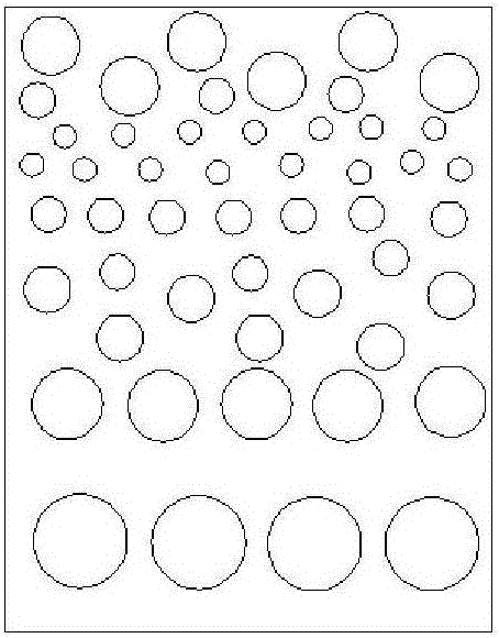
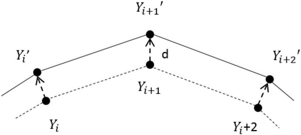
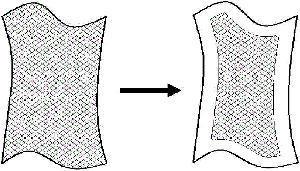
The invention relates to a manufacturing method of a personalized retaining splint for department of orthopedics. The manufacturing method comprises the following steps: conducting stress analysis on the surface of a patient's limb with fracture, so that a stress distribution situation is obtained, and forming a plurality of hollowed structures in the surface in accordance with the stress distribution situation, wherein the hollowed structures in a region with a high stress value are dense and the hollow structures in a region with a low stress value are sparse; then, deviating the surface outwards by a predetermined thickness, so that a splint model is obtained, cutting the splint model into two parts, namely an upper splint and a lower splint and filling the hollowed structures within predetermined distances from edges to central directions along the surfaces of the upper and lower splints; separately arranging connecting pieces, which are mutually matched and are used for fixedly connecting the upper and lower splints in a detachable mode, on the upper splint and the lower splint; leading data of the upper splint and the lower splint into a 3D printer and conducting printing, so that the retaining splint is manufactured. The retaining splint for the department of orthopedics manufactured by the invention is not only comfortable to wear; and moreover, the retaining splint is convenient to detach for changing dressing, cleaning and the like.

Description

technical field [0001] The invention relates to a manufacturing method of a personalized orthopedic retention splint, which belongs to the technical field of forming and connecting fixing parts. Background technique [0002] As a common motor system trauma, fractures are increasing in frequency and complexity year by year. The traditional method for postoperative rehabilitation of fractures is to fix the patient's fractures with external fixation brackets such as plaster or splints. [0003] Plaster fixation is a common method for fixing fracture patients. The advantage of plaster fixation is that it is hard and not easy to deform and loose. However, due to the vertical rigidity of the plaster cast and the tight fit with the limbs, it is difficult to adapt to the reactive swelling of the limbs after trauma, and it is easy to compress the limbs and cause many complications, such as compressive soup, compressive nerve paralysis and blood circulation disorders, etc. In severe ...

Claims


Application Information

Patent Timeline
Patent Type & Authority Applications(China)
IPC IPC(8): A61F5/058
CPCA61F5/05841
Inventor 戴宁李大伟崔海华葛志轩程筱胜
Owner NANJING UNIV OF AERONAUTICS & ASTRONAUTICS
Why Eureka
Try Eureka