Sickbed support for burn patient
A technology for patients and hospital beds, which is applied in the field of hospital bed supports, can solve the problems of easy feeling of discomfort, high probability of infection, unfavorable wound healing, etc., and achieve the effect of avoiding random movement and improving the stability of use
- Summary
- Abstract
- Description
- Claims
- Application Information
AI Technical Summary
Problems solved by technology
Method used
Image

Examples
Embodiment Construction
[0024] The present invention will be further described below in conjunction with accompanying drawing.
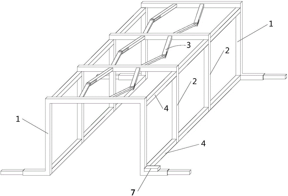
[0025] Such as figure 1 As shown, the hospital bed support for burn patients provided by the embodiment of the present invention includes two parallel and opposite main support frames 1, several auxiliary support frames 1 arranged between the two main support frames 1 and parallel to the main support frames. Support frame 2, the top of the adjacent main and auxiliary support frames and the top of the adjacent auxiliary support frame are all connected by a connecting mechanism 3, the left and right sides of the adjacent main and auxiliary support frames and the left and right sides of the adjacent auxiliary support frame are all connected. Connected by a flexible connecting rod 4.
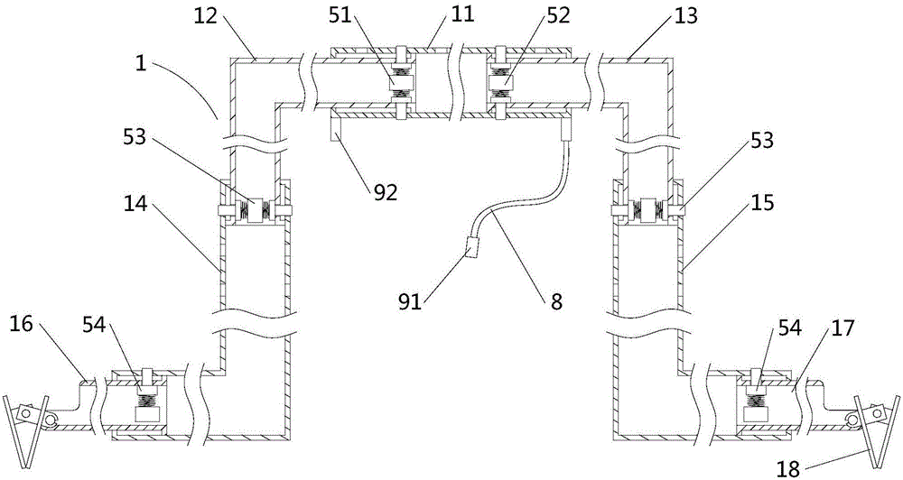
[0026] Such as figure 2 As shown, the main support frame 1 is in the shape of a "several", including a hollow main ejector rod 11, a first folding rod 12 and a second folding rod 13 connected ...
PUM
 Abstract
Description
Claims
Application Information
PatSnap Eureka turns technology decisions into work you can execute. Powered by our Innovation Knowledge Graph, it runs expert workflows across engineering, life sciences, materials and intellectual property. Get your review-ready output in minutes.


