Environment-friendly iron leftover material recycling device for buildings
A technology for recycling and construction, which is applied in the field of recycling and processing devices for environmentally friendly construction iron scraps, can solve the problems of complicated operation, low recycling efficiency, and poor effect, and achieve simple operation, high recycling efficiency, and good effect Effect
- Summary
- Abstract
- Description
- Claims
- Application Information
AI Technical Summary
Problems solved by technology
Method used
Image


Examples
Embodiment 1
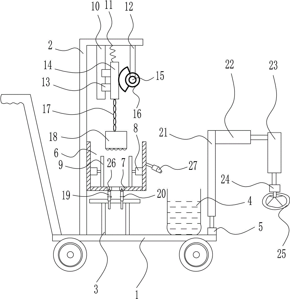
[0024] It also includes a fan 27, and the right side of the processing box 6 is provided with a fan 27.
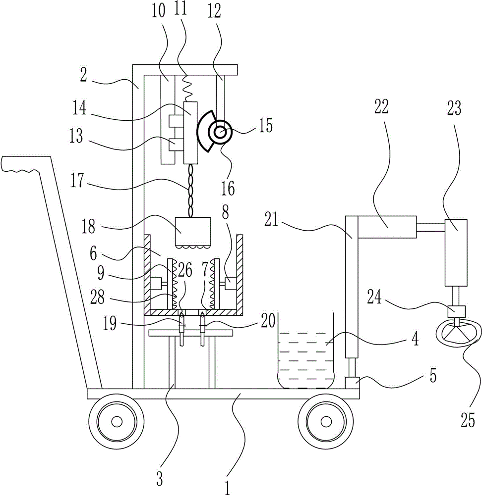
[0025] It also includes crushing teeth 28, and the pressing plate 9 is provided with crushing teeth 28.
[0026] Motor I5, motor II24, and motor III15 are servo motors.
[0027]Working principle: When using this device to recycle iron scraps, first push the trolley 1 to the construction site, and when there are iron scraps, first start the cylinder II23 to extend, and the extension of the cylinder II23 drives the motor II24 and The ring electromagnet 25 moves downwards, makes the ring electromagnet 25 contact with the ground, and then starts the cylinder I 22 to expand and contract, so that the ring electromagnet 25 touches the irony scraps, and then energizes the ring electromagnet 25, and the ring electromagnet 25 can energize the iron. Quality leftover material sucks, and after annular electromagnet 25 sucks some irony leftover material, then control cylinder II 23 ret...
PUM
 Abstract
Description
Claims
Application Information
PatSnap Eureka turns technology decisions into work you can execute. Powered by our Innovation Knowledge Graph, it runs expert workflows across engineering, life sciences, materials and intellectual property. Get your review-ready output in minutes.


