
Band sawing machine

A band saw machine and band saw technology, applied in the direction of band saws, sawing components, sawing equipment, etc., can solve the problems of affecting cutting accuracy, small conveying speed, and large impact force of the main pressing device, so as to reduce the conveying time , Improve the conveying speed and ensure the effect of cutting accuracy

Active Publication Date: 2016-09-28
HUZHOU TUOGAO MACHINERY CO LTD
View PDF9 Cites 2 Cited by
  • Summary
  • Abstract
  • Description
  • Claims
  • Application Information

AI Technical Summary

Problems solved by technology

For such a band saw machine, the sawdust generated during the cutting process is not easy to discharge and flows into the gap between the band saw blade and the cutting workpiece. First, it is easy to rub against the band saw blade to generate more heat; Cutting quality; the third is that the inertia of the workpiece to be processed is large, which will generate a large impact force on the main pressing device, which will easily cause damage to the parts and inaccurate positioning, and affect the cutting accuracy. The greater the conveying speed, the greater the impact force. Therefore, the general conveying speed is also relatively small, and the conveying efficiency is low.

Method used


Image

  • Band sawing machine
  • Band sawing machine
  • Band sawing machine

Examples


Embodiment Construction

[0023] The following specific examples are only explanations of the present invention, and it is not a limitation of the present invention. Those skilled in the art can make modifications without creative contribution to the present embodiment as required after reading this specification, but as long as they are within the rights of the present invention All claims are protected by patent law.

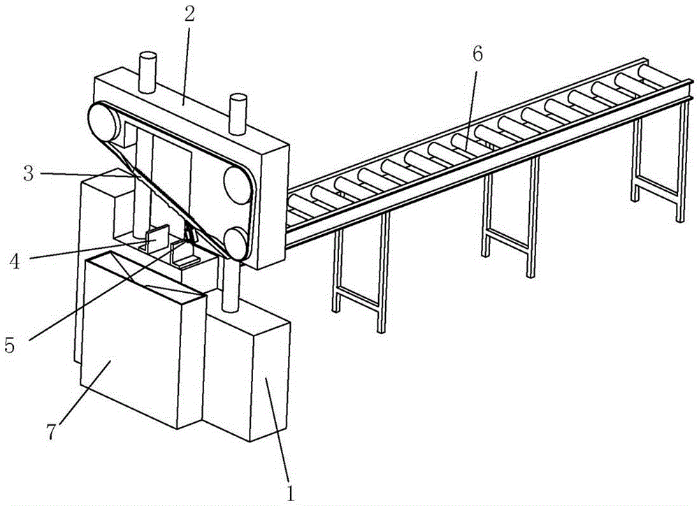
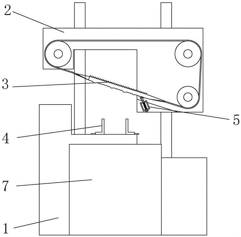
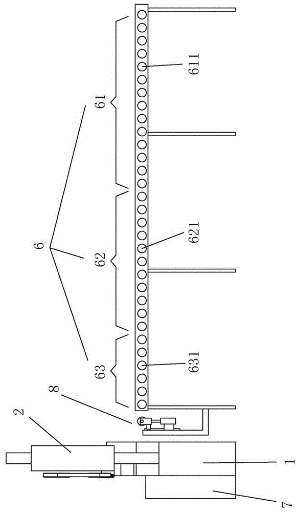
[0024] Examples such as figure 1 As shown, a band saw machine includes a base 1, a cutting seat 2 that is raised and lowered relative to the base 1, and a cutting device arranged on the cutting seat 2. The base 1 is provided with a The conveying device 6 and the fixing device 4 for fixing the wood, wherein the fixing device is two relatively movable splints.

[0025] Such as figure 1 , figure 2 with Figure 4 As shown, the cutting device includes a driving wheel and a driven wheel and a band saw 3 wound on the driving wheel and the driven wheel, the cutting direction of the band s...


PUM

PropertyMeasurementUnit
Heightaaaaaaaaaa

Abstract

The invention relates to the technical field of cutting equipment, in particular to a band sawing machine. An included angle of 20-40 degrees is formed between the cutting direction of a band saw and a horizontal direction; the band saw comprises a band saw body, sawing teeth and arc-shaped convex teeth, wherein rolling wheels which are in resisting contact with the arc-shaped convex teeth are arranged under the band saw; in the cutting direction of the band saw, a spacing between the adjacent two arc-shaped convex teeth in a last group is smaller than that between the adjacent two arc-shaped convex teeth in a next group; a first transporting roller group formed by a plurality of first transporting rollers and a third transporting roller group formed by a plurality of third transporting rollers are arranged on a transporting frame; the rotating direction of the first transporting rollers is opposite to that of the third transporting rollers. The band sawing machine disclosed by the invention is good in chip removing effect, low in calorific capacity, and good in cutting performance; not only can saw powder in sawing cracks be effectively discharged, but also the saw powder in the sawing teeth can fall down, so that a saw blade is kept clean; the initial transporting speed of wood materials can be increased, the transporting time is shortened, impacts are reduced, and cutting accuracy is guaranteed.

Description

technical field [0001] The invention relates to the technical field of cutting equipment, in particular to a band saw machine. Background technique [0002] The band saw machine is a kind of saw machine which uses the ring-shaped endless band saw blade as the saw tool, and performs unidirectional continuous linear motion around the two saw wheels to saw the workpiece. It is widely used in the field of material processing; Saw machine, including bracket, workbench, upper saw wheel, lower saw wheel, band saw blade and motor, upper saw wheel and lower saw wheel are installed on the bracket through the rotating shaft, workbench is installed on the bracket and located between the upper saw wheel and the lower saw Between the wheels, a cutting area is arranged on the workbench, and the band saw blade is annular and installed around the upper saw wheel and the lower saw wheel, and the lower saw wheel is connected with the output end of the motor. When in use, the motor drives the ...

Claims


Application Information

Patent Timeline
IPC IPC(8): B27B13/00B27B13/08B27B13/16B27G3/00B27B25/00B27B29/02
CPCB27B13/00B27B13/08B27B13/16B27B25/00B27B29/02B27G3/00
Inventor 屠丰田姜晓丽
Owner HUZHOU TUOGAO MACHINERY CO LTD
Features
  • Generate Ideas
  • Intellectual Property
  • Life Sciences
  • Materials
  • Tech Scout
  • Unparalleled Data Quality
  • Higher Quality Content
  • 60% Fewer Hallucinations
Learn More