Injection mold ejection mechanism for electroplated parts

A technology of injection mold and ejection mechanism, which is applied in the field of injection mold ejection mechanism, can solve the problems of inapplicable molding and processing of injection molding products, high requirements for product appearance, and reduced production efficiency, so as to meet the requirements of appearance guarantee, quality assurance, The effect of improving productivity

Active Publication Date: 2018-04-10
NINGBO FANGZHENG TOOL
View PDF7 Cites 0 Cited by
  • Summary
  • Abstract
  • Description
  • Claims
  • Application Information

AI Technical Summary

Problems solved by technology

[0003] 1) Since the ejection mechanism of the traditional injection mold usually sets the end face of the ejector pin on the surface of the product, the contact area is relatively large. In this way, once the injection molding is released, the surface of the ejector pin will remain However, the automotive decorative panel is a thin-walled curved surface part, and the product needs to be electroplated after injection molding. The appearance of the injected product is very demanding, and it is not allowed to leave injection marks on the surface of the product. Therefore, the ejection mechanism of the traditional injection mold cannot be applied to the molding process of this injection molded product that requires subsequent electroplating operations
[0004] 2) In addition, traditional injection molds usually set the ejection mechanism at the bottom of the lower mold assembly. After the upper mold assembly is opened, the ejection operation of the ejector mechanism is performed to eject the product from the lower mold, but As a result, the entire mold appears huge, complex in structure, and demoulding is slow, reducing production efficiency

Method used


Image

  • Injection mold ejection mechanism for electroplated parts
  • Injection mold ejection mechanism for electroplated parts

Examples


Embodiment Construction

[0026] The present invention will be described in further detail below in conjunction with the accompanying drawings and specific embodiments.

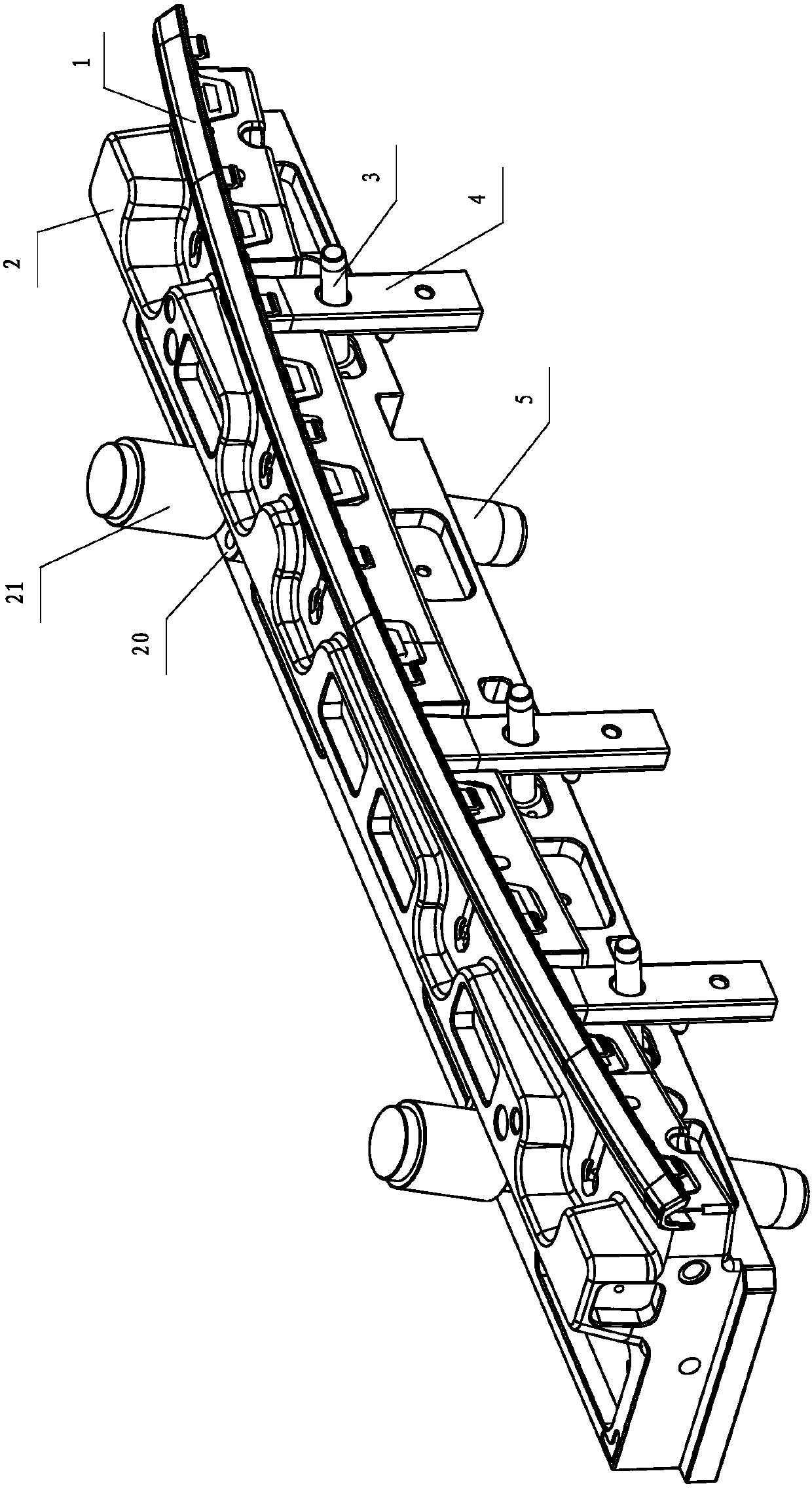
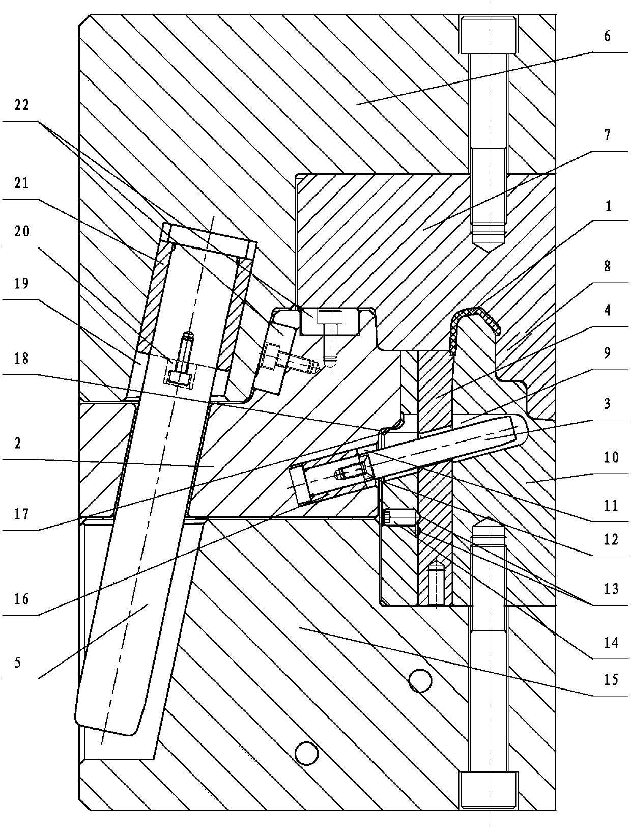
[0027] Depend on figure 1 with figure 2 It can be seen from the schematic structural diagram of the ejection mechanism of the injection mold for the electroplating part of the present invention that it includes the bullet block 4 and a driving mechanism for driving the bullet block 4 to move up and down for demoulding. The bullet blocks 4 are multiple and arranged along the length direction of the product. The corners of the upper end surface of the bullet blocks 4 are part of the thin-walled edge of the product. The bullet blocks 4 are vertically slidably connected to the lower mold of the injection mold. within the component. The drive mechanism includes a slider 2, a slider slanted guide post 5 and an elastic block slanted guide post 3, the slider 2 is slidably connected to the lower mold assembly in the horizontal direction, an...


PUM


Abstract

The invention discloses an ejection mechanism for an injection mold for electroplated parts. The ejection mechanism comprises ejection blocks (4) and a driving mechanism used for driving the ejection blocks (4) to vertically move for being released from the mold; the ejection blocks (4) are connected inside a lower mold assembly of the injection mold in a sliding mode in the vertical direction; the driving mechanism comprises a sliding block (2), sliding block inclination guide columns (5) and ejection block inclination guide columns (3), wherein the sliding block (2) is connected to the lower mold assembly in a sliding mode in the horizontal direction, the upper ends of the sliding block inclination guide columns (5) are fixedly connected to an upper mold assembly, the lower ends of the sliding block inclination guide columns (5) are connected to the sliding block (2) in a sliding mode and drive the sliding block (2) to slide towards the outer side of the injection mold in the mold opening process, one ends of the ejection block inclination guide columns (3) are fixedly connected inside the sliding block (2), and the other ends of the ejection block inclination guide columns (3) are connected to the ejection blocks (4) in a sliding mode and drive the ejection blocks (4) to slide upwards for ejecting products in the mold opening process. According to the structure, ejection marks are prevented from being left on surfaces of the products, the appearance requirement of subsequent electroplating is met, and the quality requirement of the products is met.

Description

technical field [0001] The invention relates to the technical field of molds, in particular to an injection mold ejection mechanism for electroplating parts. Background technique [0002] With the development of the automobile industry, electroplated parts are used in many places on the interior and exterior panels of automobiles, such as car logos, door handles, and some decorative strips embedded in automobile door panels. These electroplated parts are not only for the overall aesthetic consideration of the car, but also for the purpose of lightweighting. The car electroplated parts are made of plastic materials through mold injection molding, and then electroplated with a layer of copper, nickel, chromium and other electroplating layers on the outside. The automotive trim panels made of plastics in the prior art are usually formed by injection moulds. The injection molds usually include an upper mold assembly, a lower mold assembly and an ejection mechanism, and the upper...

Claims


Application Information

Patent Timeline
Patent Type & Authority Patents(China)
IPC IPC(8): B29C45/40B29C45/33
CPCB29C45/33B29C45/4005
Inventor 王一栋胡迪金伟俞方敏应可国陈晨
Owner NINGBO FANGZHENG TOOL
Why Eureka
Try Eureka