Lock core mechanism

A technology of lock cylinder and lock cylinder, which is applied to building locks, lock shells, building structures, etc., can solve the problems of short service life, poor wear resistance, inconvenient operation, etc., and achieve a simple, reasonable and compact internal structure, which meets the needs of installation. Space requirements, simple effect of mechanical transmission connection

Active Publication Date: 2016-09-28
NANJING EASTHOUSE ELECTRIC CO LTD
View PDF7 Cites 4 Cited by
  • Summary
  • Abstract
  • Description
  • Claims
  • Application Information

AI Technical Summary

Problems solved by technology

[0003] The traditional lock cylinder structure is generally placed separately, and it is difficult to cooperate with the electronic lock. It is rarely used directly on the electronic lock to cooperate with other structures of the electronic lock. In addition, most electronic lock manufacturers place the lock cylinder separately, such as the bottom of the lock body. Too hidden and inconvenient to operate, which reduces the user experience of the product and cannot meet customer needs
In addition, the parts of traditional electronic locks are mostly stamped with powder alloy materials, which have the characteristics of low hardness, weak strength, poor wear resistance, large friction resistance, and short service life, which greatly affect the overall performance of the lock and the weather resistance of the lock. , making it unable to adapt to different climatic conditions, prone to failure, and unable to work normally in harsher climates

Method used


Image

  • Lock core mechanism
  • Lock core mechanism
  • Lock core mechanism

Examples


Embodiment Construction

[0024] The technical solution of the present invention will be further described below in conjunction with the accompanying drawings.

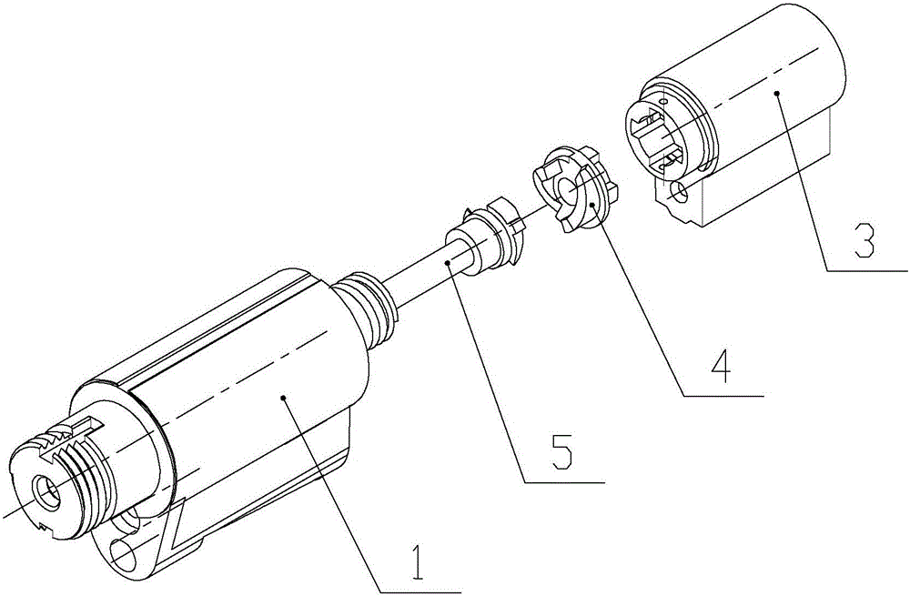
[0025] like figure 1 and Figure 4 As shown, the present invention discloses a lock cylinder mechanism, which includes a lock cylinder shell 1 and a clutch part 2, the inner wall of the lock cylinder shell 1 is a hollow structure, and the outer wall of one end of the lock cylinder shell 1 is provided with a thread 8, which is convenient for the lock cylinder shell to be screwed into In other parts of the electronic lock, it is used in conjunction with other parts; the outer wall of the other end of the lock casing 1 is provided with a handle 9, which is convenient for the key to unlock, and the user unscrews the lock to complete the unlock.

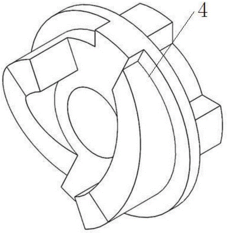
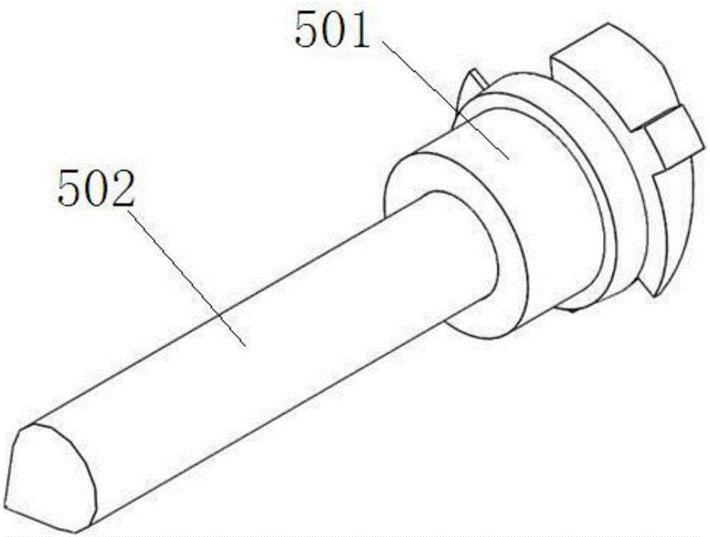
[0026] The cylinder lock housing 1 of the present invention is provided with a cylinder lock 3, a cam 4, and a clutch ejector 5 connected in sequence, such as figure 2 and image 3 shown. The cam 4 i...


PUM


Abstract

The invention discloses a lock core mechanism. The lock core mechanism comprises a lock chamber shell and a clutch part, wherein a lock chamber, a cam positioned inside the lock chamber, and a clutch ejector part which are sequentially connected are arranged inside the lock chamber shell; the clutch ejector part comprises a clamping end which is combined with the cam in a clamping manner and an ejector shaft; a reset spring is arranged on the ejector shaft in a sleeving manner, and stretches into the clutch part; a dowel is arranged in the clutch part; and when a key is inserted into the lock chamber and drives the cam to rotate, the cam pushes the clutch ejector part to perform axial linear motion in a clutch manner to eject the dowel to achieve unlocking. According to the lock core mechanism, the rotating motion of the key is converted into the linear motion of the ejector shaft through the combined structure of the cam and the clutch ejector part, and the ejector shaft ejects the dowel to achieve unlocking; and the rotating motion of the key is converted into the linear motion of the ejector shaft, so that the mechanical transmission connection of the lock core mechanism is more simple, efficient and reliable, and the safety of the lock core mechanism is improved.

Description

technical field [0001] The invention relates to a lock cylinder, in particular to a lock cylinder mechanism. Background technique [0002] Locks are widely used in homes and offices. In recent years, with the rapid development of electronic technology, the traditional lock production has undergone earth-shaking changes. The combination of modern electronic technology and mechanical technology has produced a large number of products such as voice-activated locks and magnetic locks. Advanced electronic locks such as controlled locks, combination locks, remote control locks, and fingerprint locks. [0003] The traditional lock cylinder structure is generally placed separately, and it is difficult to cooperate with the electronic lock. It is rarely used directly on the electronic lock to cooperate with other structures of the electronic lock. In addition, most electronic lock manufacturers place the lock cylinder separately, such as the bottom of the lock body. It is too concea...

Claims


Application Information

Patent Timeline
Patent Type & Authority Applications(China)
IPC IPC(8): E05B47/00E05B15/00E05B9/04
CPCE05B9/04E05B15/00E05B47/00E05B2047/0024E05B2047/0026
Inventor 闵浩石存平
Owner NANJING EASTHOUSE ELECTRIC CO LTD
Why Eureka
Try Eureka