
Shell-tube type dripping heat exchanger

A heat exchanger, shell-and-tube technology, applied in the field of heat exchangers, can solve the problems of increased manufacturing and material costs, increased possibility of errors, complex distributor structure, etc., and achieves the effect of simple structure and less man-hours for production

Inactive Publication Date: 2016-09-28
胡建英
View PDF8 Cites 0 Cited by
  • Summary
  • Abstract
  • Description
  • Claims
  • Application Information

AI Technical Summary

Problems solved by technology

[0004] In the mainstream design of the current shell-and-tube drip heat exchanger distributor, for example: Chinese utility model patent No. 200420029042.X "Single-tube shell-and-tube heat exchanger with distributor", Chinese utility model patent No. 200920185761. "Distributor for Flooded Evaporator", Chinese Utility Model Patent No. 201020674475.6 "Shell and Tube Heat Exchanger", Chinese Invention Patent No. 201310640265.3 "A Distributor for Shell and Tube Heat Exchanger", All of them use various measures to make the mass flow rate of refrigerant flowing out of each flow port equal, so the structure of the distributor is very complicated. On the one hand, it increases the cost of manufacturing and materials, and on the other hand, it increases the possibility of errors in the production process.

Method used


Image

  • Shell-tube type dripping heat exchanger
  • Shell-tube type dripping heat exchanger
  • Shell-tube type dripping heat exchanger

Examples


Embodiment Construction

[0023] In order to better understand the present invention, the invention will be described in detail below in conjunction with the accompanying drawings and specific examples.

[0024] The invention relates to a heat exchanger in the refrigeration industry, in particular to a horizontally installed shell-and-tube drip heat exchanger.

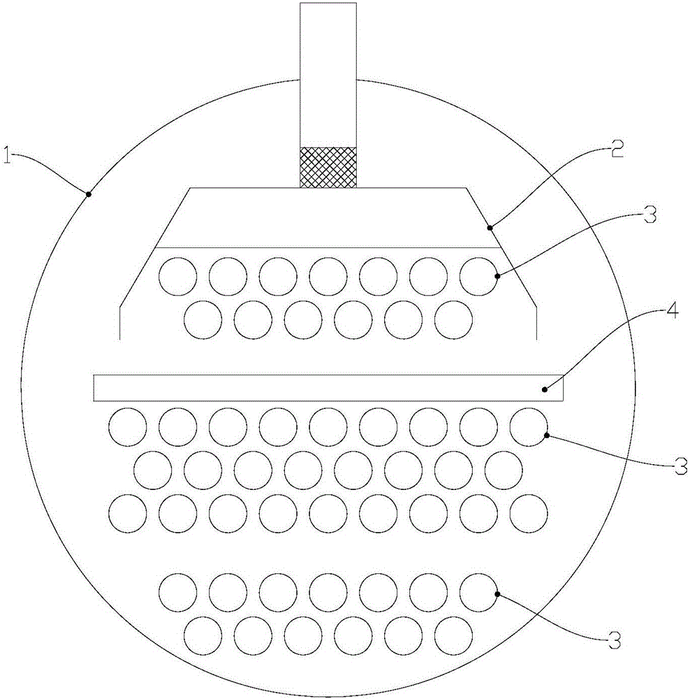
[0025] see figure 1 , The first preferred embodiment of the present invention provides a shell-and-tube drip heat exchanger, including a heat exchanger cylinder 1 , a distributor 2 , a heat exchange tube 3 and a liquid collector 4 . Distributor 2 , heat exchange tube 3 and liquid collector 4 are arranged in cylinder body 1 . After being distributed by the distributor 2 , the refrigerant enters the cylinder 1 and undergoes a heat exchange reaction with the brine in the heat exchange tube 3 . The liquid collector 4 is arranged between the tube groups of the heat exchange tubes 3, and collects the refrigerant before distributing it. The liquid ...


PUM


Abstract

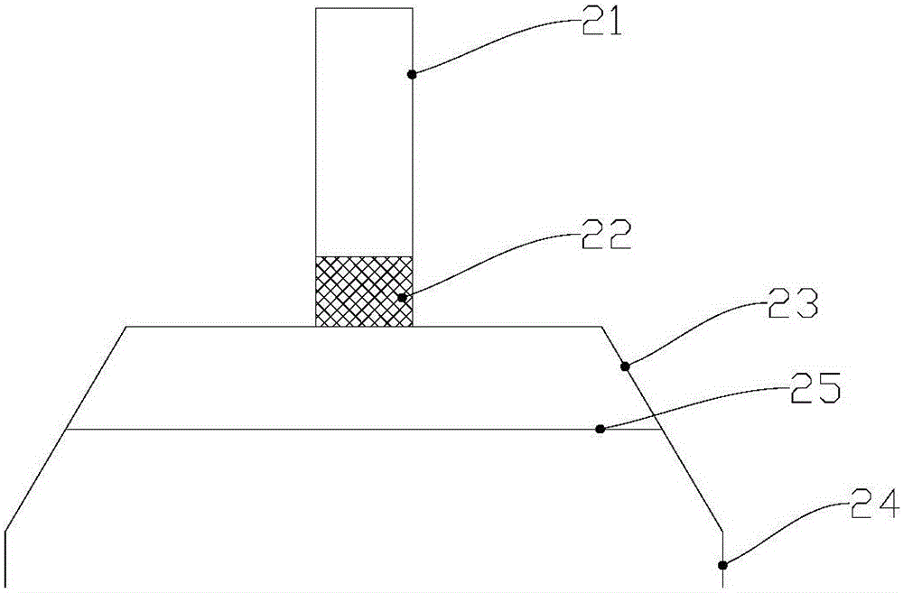
The invention provides a shell-and-tube dripping heat exchanger, which includes a heat exchanger cylinder, a distributor, a heat exchange tube and a liquid collector, and the distributor, heat exchange tube and liquid collector are arranged in the cylinder , the liquid collector is arranged between the tube groups of the heat exchange tubes. The distributor includes a liquid inlet, a filter screen, a cover plate, a liquid baffle, and a distribution plate, the liquid inlet is arranged outside the heat exchanger cylinder, and the filter mesh is arranged below the liquid inlet , the cover plate is set under the filter screen, the liquid baffle plate is set on both sides of the cover plate, the distribution plate is set under the cover plate and the two ends are against the cover plate Next, the distribution plate has a plurality of flow ports equally spaced along its width direction. In the shell-and-tube dripping heat exchanger of the present invention, a distributor with a very simple structure is arranged above the heat exchange tube group. The distributor has only one layer of distribution plates, and the structure is very simple, so less man-hours are required for manufacture.

Description

【Technical field】 [0001] The invention relates to the field of heat exchangers, in particular to a shell and tube heat exchanger. 【Background technique】 [0002] At present, shell and tube heat exchangers are often used in air conditioning or chiller refrigeration equipment. The working principle of the shell-and-tube heat exchanger is: the refrigerant goes through the shell side (single shell side), the refrigerant goes through the tube side (single-pass or multi-pass), and the two fluids exchange heat through the heat transfer tube wall. The liquid refrigerant evaporates into a gaseous state through the heat exchange tube wall and the liquid refrigerant to complete the heat exchange process. [0003] According to the above heat exchange principle, in the shell and tube heat exchanger, whether the heat exchange between the refrigerant and the brine is sufficient directly affects the heat exchange performance of the unit. [0004] In the mainstream design of the current sh...

Claims


Application Information

Patent Timeline
IPC IPC(8): F28D3/02F28D3/04
CPCF28D3/02F28D3/04
Inventor 胡建英
Owner 胡建英
Learn More