Genetic particle swarm multi-disciplinary design optimization algorithm-based guided missile parameter design method

An optimization algorithm and parameter design technology, applied in the direction of genetic law, calculation, genetic model, etc., can solve the problem of too many design parameters, and achieve the effect of reducing repeated design links, improving design efficiency, and shortening development time.

Active Publication Date: 2016-09-28
HARBIN INST OF TECH
View PDF6 Cites 11 Cited by
  • Summary
  • Abstract
  • Description
  • Claims
  • Application Information

AI Technical Summary

Problems solved by technology

[0005] The present invention aims to solve the problem that the existing missile parameter design method based on intelligent optimization algorithm is not applicable to the situation where there are many design parameters and variable coupling phenomenon under multidisciplinary

Method used


Image

  • Genetic particle swarm multi-disciplinary design optimization algorithm-based guided missile parameter design method
  • Genetic particle swarm multi-disciplinary design optimization algorithm-based guided missile parameter design method
  • Genetic particle swarm multi-disciplinary design optimization algorithm-based guided missile parameter design method

Examples


specific Embodiment approach 1

[0043] The missile parameter design method based on the genetic particle swarm multidisciplinary design optimization algorithm includes the following steps:

[0044] Step 1. Select the following design variables as design parameters:

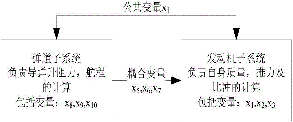
[0045] Engine throat diameter x 1 , engine combustion surface area x 2 , engine charge thickness x 3 , missile outer diameter x 4 , engine specific impulse x 5 , engine mass x 6 , fuel mass x 7, root chord length x 8 , tail root tip length x 9 , tail tip chord length x 10 ;

[0046] Combining Aerodynamics, Kinetics and Ballistics, based on fuel weight x 7 Restricted, integrate the motion equation of the missile in the horizontal plane to obtain the total range of the missile trajectory, which is the objective function F(X i );

[0047] The following design constraints exist:

[0048] (1) Select the missile end-of-flight speed Ma=1.4 as the termination condition, reduce the overload requirement at this time, and set the available ove...

specific Embodiment approach 2

[0074] According to the fuel weight x described in step 1 of this embodiment 7 The specific process of restricting the integration of the motion equation of the missile in the horizontal plane to obtain the total range of the missile trajectory is as follows:

[0075] Step 1.1, pneumatic calculation:

[0076] The total lift coefficient of the projectile is:

[0077] C y =C yW +C yT +C yB

[0078] In the formula, C yW is the lift coefficient of the wing; C yT is the lift coefficient of the projectile acting on the empennage; C yB is the lift coefficient of the projectile;

[0079] Step 1.2, power calculation:

[0080] The zero-dimensional internal ballistic differential equation of solid rocket motor used for internal ballistic calculation is:

[0081] V c dρ c dt ′ = ρ ...

specific Embodiment approach 3

[0102] C described in step 1.1 of this embodiment yW 、C yT 、C yB The calculation process is as follows:

[0103] C y W = K W · S W S B C y T = K T · S T S B ...


PUM


Abstract

The invention discloses a genetic particle swarm multi-disciplinary design optimization algorithm-based guided missile parameter design method, relates to a guided missile parameter design method, and aims at solving the problem that the conventional intelligent optimization algorithm-based guided missile parameter design method is not suitable for the conditions of more multi-disciplinary design parameters and variable coupling phenomenon. The method comprises the following steps: selecting an engine throat diameter, an engine combustion surface area, an engine charge thickness, a guided missile outer diameter, an engine specific impulse, engine mass, fuel mass, a missile wing root chord length, an empennage root tip length and an empennage tip chord length as design parameters; and optimizing three control parameters w, c1 and c2 and design parameters in a standard particle swarm algorithm by utilizing a genetic algorithm, and introducing a genetic thought into a particle swarm position updating process when optimizing the particle swarm algorithm in the optimization process. The method disclosed in the invention is suitable for the field of guided missile parameter design.

Description

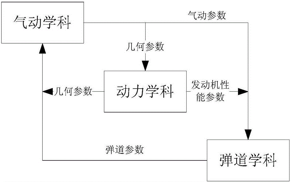
technical field [0001] The invention relates to a missile parameter design method. Background technique [0002] Many disciplines are involved in the design of aircraft. From the perspective of the overall system, there must be a certain degree of interaction and coupling effect among the various subsystems. Since the subsystems have their own independent analysis and design tools, the traditional sequential design often cannot be considered comprehensively, thus failing to fully consider the coupling factors between the various systems. Applying multidisciplinary design optimization to solve the design problems of the above-mentioned overall system not only improves the design efficiency, but also improves the performance of the product. [0003] Missile weapon design requires comprehensive knowledge of multiple disciplines such as aerodynamics, ballistics, and power. With the development of the design level, it is necessary to carry out multidisciplinary comprehensive de...

Claims


Application Information

Patent Timeline
Patent Type & Authority Applications(China)
IPC IPC(8): G06F17/50G06N3/12
CPCG06F30/17G06N3/126
Inventor 郭继峰关英姿荣思远赵毓
Owner HARBIN INST OF TECH
Why Eureka
Try Eureka