
Optimal configuration method of DC magnetic bias treatment device

A DC bias and optimized configuration technology, applied in the field of UHV DC, can solve the problems of high price of DC bias control equipment, affecting the operation of the AC power grid, and redundant configuration of equipment, so as to reduce the number of equipment installed, reduce the workload, The effect of improving operational reliability

Active Publication Date: 2016-09-28
STATE GRID CORP OF CHINA +2
View PDF3 Cites 4 Cited by
  • Summary
  • Abstract
  • Description
  • Claims
  • Application Information

AI Technical Summary

Problems solved by technology

[0004] Therefore, the DC bias control equipment configuration scheme obtained by simply calculating or measuring the DC current distribution can achieve the purpose of reducing the DC current at the neutral point of the transformer. However, there is a possibility of redundant configuration of the equipment
In addition, the DC bias control equipment is expensive and requires the maintenance and management of on-site operation and maintenance personnel. Once the equipment operates abnormally, the operation reliability of the equipment may also affect the operation of the AC power grid.

Method used


Image

  • Optimal configuration method of DC magnetic bias treatment device
  • Optimal configuration method of DC magnetic bias treatment device
  • Optimal configuration method of DC magnetic bias treatment device

Examples


Embodiment

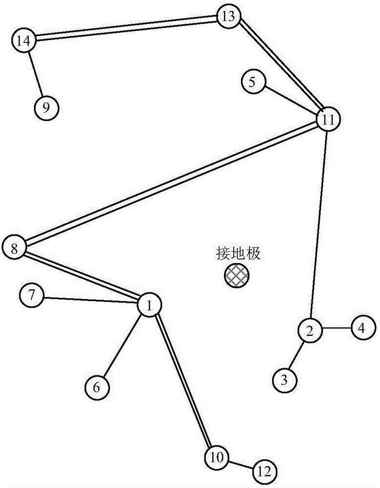
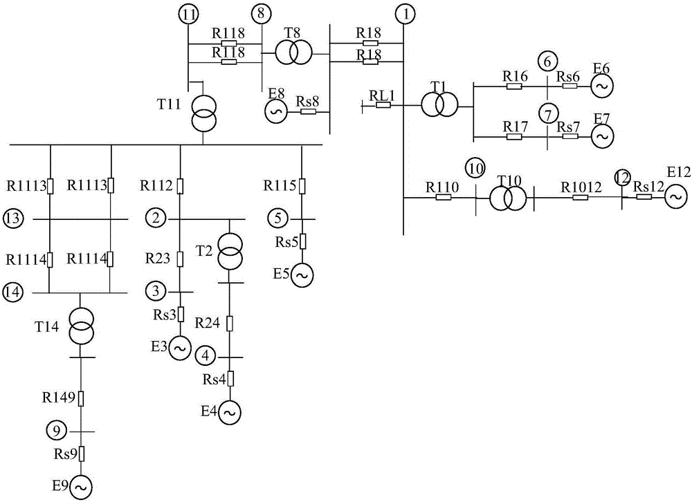
[0055] Taking DC bias control equipment in a substation around a UHV grounding pole as an example, first use CDEGS software to simulate and calculate the potential of the grounding point, and input the grounding pole parameters, soil parameters around the grounding pole, and grounding pole grounding current in the software. The earth potential distribution law can be calculated. Secondly, the AC system simulation model based on PSCAD / EMTDC is built with the DC ground pole as the center. The impact of injecting current into the DC ground electrode on the AC transformer is equivalent to connecting a DC voltage source at the neutral point of the transformer. Created in PSCAD as figure 2 The simulation model shown, wherein, the simulation circuit diagram of the simulation model is as image 3 shown. Since the AC system that may be affected by the unipolar grounding operation of the DC system is limited to a certain range, the AC system only needs to build a partial system mode...


PUM


Abstract

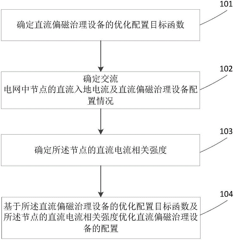
The invention relates to an optimal configuration method of a DC magnetic bias treatment device. The optimal configuration method comprises the steps of determining an optimal configuration target function of the DC magnetic bias treatment device; determining a DC grounding current of a node in a power grid and a configuration condition of the DC magnetic bias treatment device; determining a DC current correlation intensity of the node; and optimizing the configuration condition of the DC magnetic bias treatment device based on the optimal configuration target function of the DC magnetic bias treatment device and the DC current correlation intensity of the node. The optimal configuration method of the DC magnetic bias treatment device is based on the concept of the correlation intensity, and is to sequence nodes of an AC system according to the correlation intensities obtained through calculation and enable devices at the nodes with weak correlation intensities in the existing initial configuration scheme to be retreated successively, so that the number of the DC magnetic bias treatment devices is greatly reduced.

Description

technical field [0001] The invention relates to the field of UHV DC, in particular to an optimal configuration method of DC bias control equipment. Background technique [0002] In order to solve the DC bias problem of the AC system transformer near the UHV DC grounding pole, the method of connecting the DC bias control equipment to the neutral point of the grounded AC system transformer is generally used to suppress or isolate the DC current. The configuration of the DC bias control equipment is determined according to the actual engineering measurement value or simulation calculation of the neutral point DC current of the transformer. [0003] The distribution of DC current in the AC system determines the configuration of the suppression bias equipment, and the switching on and off of the DC bias control equipment directly affects the distribution of DC current in the AC system. The two are interrelated. In the process of configuring equipment, the switching on and off of...

Claims


Application Information

Patent Timeline
IPC IPC(8): G06F17/50
CPCG06F2111/06G06F30/367Y02E60/00
Inventor 王冬青王天正曹楠李冰刘振富马晓光陈翔宇郭文明侯鹏
Owner STATE GRID CORP OF CHINA
Learn More