

Battery voltage-multiplying charging circuit and mobile terminal
A charging circuit and mobile terminal technology, applied in battery circuit devices, electric vehicles, circuit devices, etc., can solve problems such as heating of the battery body, and achieve the effect of increasing the charging speed
- Summary
- Abstract
- Description
- Claims
- Application Information
AI Technical Summary
Problems solved by technology
Method used
Image

Examples
Embodiment 1
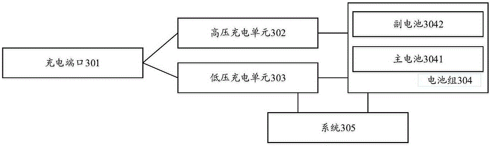
[0020] refer to image 3 , shows a schematic diagram of a battery voltage doubler charging circuit according to Embodiment 1 of the present invention.
[0021] The battery voltage doubler charging circuit in the embodiment of the present invention includes: a charging port 301, a high-voltage charging unit 302, a low-voltage charging unit 303, a battery pack 304, and a system 305, wherein the battery pack 304 includes a main battery 3041 and a secondary battery 3042 .
[0022] Wherein, the high-voltage charging unit 302 and the low-voltage charging unit 303 are respectively connected to the charging port 301 , the low-voltage charging unit 303 is connected to the system 305 and the battery pack 304 respectively; the high-voltage charging unit 302 is connected to the battery pack 304 .
[0023] When performing fast charging, the main battery 3041 and the auxiliary battery are switched to a series connection state, the charging voltage is transmitted to the high-voltage chargin...
Embodiment 2
[0031] refer to Figure 4 , shows a schematic diagram of a battery voltage doubler charging circuit according to Embodiment 2 of the present invention.
[0032] Such as Figure 4 As shown, the battery voltage doubler charging circuit provided by the embodiment of the present invention includes: a charging port (Charging port), a high-voltage charging unit (High voltage PMIC), a low-voltage charging unit, a battery pack, and a system, wherein the battery pack includes a main battery (Main battery) And a secondary battery, Sendbattery; the low-voltage charging unit is a normal charging unit Nomal PMIC, which provides regular mode charging for the battery pack.
[0033] Such as Figure 4 As shown, the high-voltage charging unit and the low-voltage charging unit in the battery voltage doubler charging circuit are respectively connected to the charging port, the low-voltage charging unit is connected to the system and the battery pack, and the high-voltage charging unit is also c...
PUM
 Abstract
Description
Claims
Application Information