Permanent magnetic vernier motor

A vernier motor and permanent magnet technology, applied in the direction of magnetic circuits, electromechanical devices, electrical components, etc., can solve the problems of low motor space utilization, low motor material utilization, low torque density, etc., to improve space utilization and , enhance the reliability and fault-tolerant operation of the system, and improve the effect of torque and power level

Active Publication Date: 2016-09-28
SHENZHEN UNIV
View PDF4 Cites 17 Cited by
  • Summary
  • Abstract
  • Description
  • Claims
  • Application Information

AI Technical Summary

Problems solved by technology

[0004] The object of the present invention is to overcome at least one disadvantage of the above-mentioned prior art, and provides a permanent magnet vernier motor, which solves the problem of low air gap harmonic field utilization, low torque density, and motor problems in the existing permanent magnet vernier motor. Technical problems of low space utilization, low utilization of motor materials, and poor reliability of motor fault-tolerant operation

Method used


Image

  • Permanent magnetic vernier motor
  • Permanent magnetic vernier motor
  • Permanent magnetic vernier motor

Examples


Embodiment 1

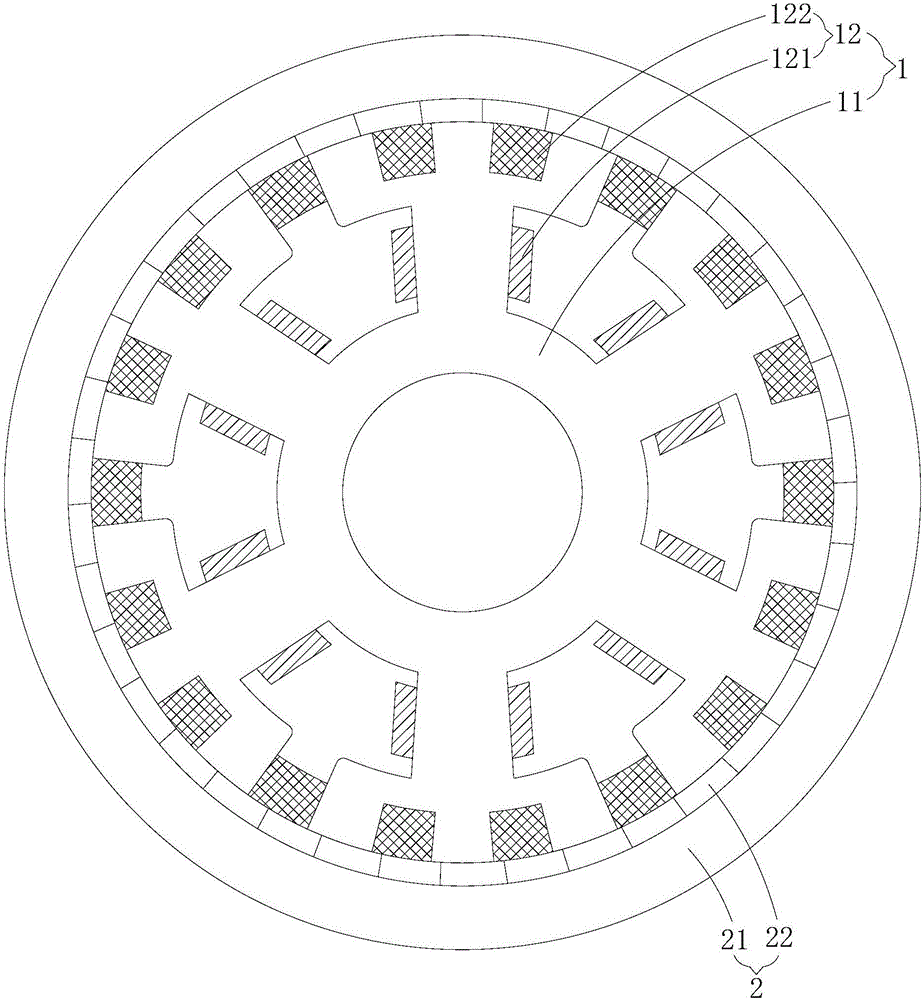
[0030] Such as Figure 1-4 As shown, the permanent magnet vernier motor provided by Embodiment 1 of the present invention includes a stator 1 and a rotor 2 that rotates with the stator 1. The stator 1 includes a stator core 11 and a stator winding 12 arranged on the stator core 11. The rotor 2 Including the rotor core 21 and the permanent magnet 22 arranged on the rotor core 21, the stator winding 12 includes a first set of windings 121 and a second set of windings 122, the first set of windings 121 and the second set of windings 122 operate independently of each other, and The number of pole pairs of the first set of windings 121 is greater or smaller than the number of pole pairs of the second set of windings 122 , that is, the number of pole pairs of the first set of windings 121 and the number of pole pairs of the second set of windings 122 are not equal. Both the first set of windings 121 and the second set of windings 122 can be single-phase windings or multi-phase windi...

Embodiment 2

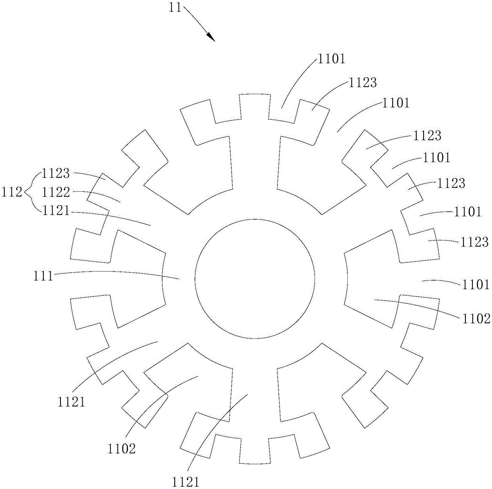
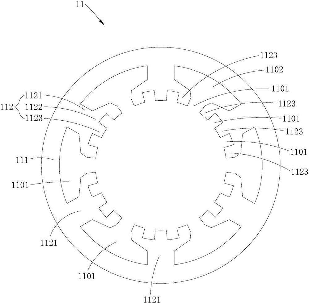
[0043] Such as Figure 5 and Figure 6 As shown, the main difference between the permanent magnet vernier motor provided in this embodiment and the first embodiment is that the stator 1 in the first embodiment is a split-pole stator structure, and the first set of windings 121 and the second set of windings 122 are along the The stator core 11 is radially distributed inside and outside; while the stator 1 in this embodiment is an open slot stator structure, specifically, the stator core 11 in this embodiment includes a stator yoke 111 and several circumferentially spaced The protruding teeth 113 on the stator yoke 111, the stator yoke 111 is a circumferentially closed ring structure, the protruding teeth 113 are protruded on the inner or outer side of the stator yoke 111, and a notch is formed between any two adjacent protruding teeth 113 1101 , the first set of windings 121 and the second set of windings 122 are distributed in each slot 1101 . In this embodiment, the first ...

Embodiment 3

[0047] Such as Figure 7 As shown, the main difference between the permanent magnet vernier motor provided in this embodiment and the first and second embodiments is that the installation methods of the first magnet 221 and the second magnet 222 are different. Specifically, in Embodiment 1 and Embodiment 2, each first magnet 221 and each second magnet 222 are attached and fixed on the surface of the rotor core 21, and each first magnet 221 and each second magnet 222 are exposed on the The surface of the rotor core 21; and in the present embodiment, each first magnet 221 and each second magnet 222 are inserted and fixed in the rotor core 21, and the surface of the rotor core 21 is provided with several magnets for each first magnet respectively. The magnets 221 and the second magnets 222 are inserted into the fixed installation slots, and only one surface of each first magnet 221 and each second magnet 222 is flush with the surface of the rotor core 21 . Specifically, when the...


PUM


Abstract

The invention is applied to the technical field of a motor structure, and discloses a permanent magnetic vernier motor. The permanent magnetic vernier motor comprises a stator and a rotor rotationally cooperating with the stator, wherein the stator comprises a stator iron core and a stator winding arranged on the stator iron core, the rotor comprises a rotor iron core and a permanent magnet arranged on the rotor iron core, the stator winding comprises a first winding and a second winding, the first winding and the second winding mutually independently run, and the number of pole-pairs of the first winding is greater or smaller than the number of pole-pairs of the second winding. According to the invention, through additional arrangement of one more winding on the basis of a conventional single-stator iron core and a single stator winding , a useful harmonic magnetic field in an air gap is fully utilized, such that under the condition that the motor structure complexity is not increased, the space utilization rate of the motor and the utilization rate of a motor material are effectively improved, the torque and the power grade of the motor are improved accordingly, and the system operation reliability and the fault tolerance operation capability of the motor are effectively enhanced.

Description

technical field [0001] The invention belongs to the field of motors, in particular to a permanent magnet vernier motor. Background technique [0002] As a low-speed and high-torque direct-drive motor, permanent magnet vernier motor has broad application prospects in new energy fields such as electric vehicles, wind power generation, and wave power generation. The permanent magnet vernier motor generally includes a rotor core, a permanent magnet, a stator core and a stator winding. The stator core is provided with a magnetic modulation block, which has a magnetic field modulation function. The high-speed design of the hub. [0003] However, the existing permanent magnet vernier motors still have deficiencies in specific applications, which are specifically reflected as follows: the existing permanent magnet vernier motors are generally single-stator iron-core, single-stator winding motors, so it is difficult to make full use of the air gap The rich and useful harmonic magne...

Claims


Application Information

Patent Timeline
Patent Type & Authority Applications(China)
IPC IPC(8): H02K1/27H02K1/16H02K1/14H02K3/28
CPCH02K1/14H02K1/16H02K1/2706H02K3/28
Inventor 李文龙李坚强明仲
Owner SHENZHEN UNIV
Why Eureka
Try Eureka