Combustor structure for gas stove

A technology for burners and gas stoves, which is applied in the direction of gas fuel burners, burners, and combustion methods. Effect of improving thermal efficiency and increasing heat load

Inactive Publication Date: 2016-10-05
浙江布鲁尼电器科技有限公司
View PDF8 Cites 4 Cited by
  • Summary
  • Abstract
  • Description
  • Claims
  • Application Information

AI Technical Summary

Problems solved by technology

[0006] However, the structure of the above scheme is relatively complicated, and there is no improvement in the connection between the injector and the burner body to improve the combustion efficiency

Method used


Image

  • Combustor structure for gas stove
  • Combustor structure for gas stove
  • Combustor structure for gas stove

Examples


Embodiment 1

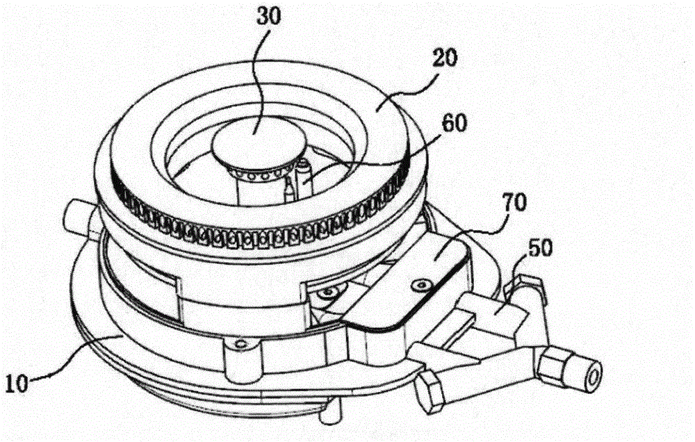
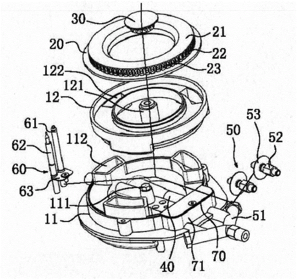
[0026] Such as figure 1 and figure 2 As shown, a burner structure for a gas stove includes a base 10, the base 10 is detachably connected with an outer fire cover 20 and an inner fire cover 30, and the base 10 is provided with at least two Each ejector 40, and the gas outlet of each ejector 40 is located in the base 10 and communicates with the outer fire cover 20 and the inner fire cover 30 through the base 10, so that the gas in each ejector 40 can be Enter into the outer fire cover 20 and the inner fire cover 30 to burn respectively. That is to say, the gas mixed with air once in each injector 40 can enter the outer fire cover 20 and the inner fire cover 30 to burn respectively, which not only increases the heat load, but also makes the combustion of the gas more complete and the thermal efficiency higher .

[0027] The base 10 includes a lower base 11 and an upper base 12 sleeved on the lower base 11. The upper base 12 and the lower base 11 are tightly connected, and t...

Embodiment 2

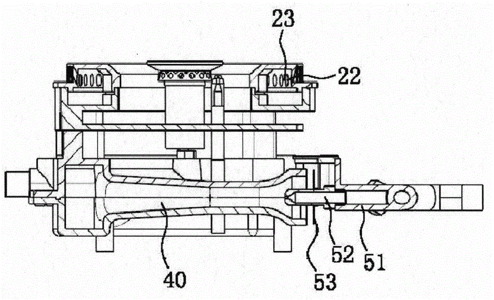
[0036] The structure of this embodiment is basically the same as that of Embodiment 1, the difference is that the primary air volume adjustment mechanism 50 includes two straight pipes, and the two straight pipes are respectively connected to the intake end of an ejector 40. The connection with the ejector 40 is provided with a nozzle 52 detachably connected to the straight pipe. The mouth of the nozzle 52 extends to the inside of the ejector 40. The outer wall of the nozzle 52 is screwed with a flap 53, and the flap 53 can move along the The outer wall of the nozzle 52 is rotated so as to adjust the distance between the flap 53 and the air inlet end of the ejector 40 .


PUM


Abstract

The invention belongs to the technical field of gas stoves and relates to a combustor structure for a gas stove. According to the combustor structure, the technical problems of low thermal load and efficiency in the prior art are solved. The combustor structure comprises a base, wherein an outer flame cover and an inner flame cover are detachably connected to the base, at least two ejectors are arranged in the base, an air outlet end of each ejector is located in the base and is simultaneously communicated with the outer flame cover and the inner flame cover through the base, and therefore, fuel gas in each ejector can respectively enter the outer flame cover and the inner flame cover to be combusted. The combustor structure is high in thermal efficiency and load, and the combustion is adequate.

Description

technical field [0001] The invention belongs to the technical field of gas stoves, and relates to a burner for a stove, in particular to a burner structure for a gas stove. Background technique [0002] Civil stoves all use the atmospheric combustion method, because this kind of burner is pre-mixed with part of the air, which makes the combustion flame short, strong firepower, high temperature, and the combustion efficiency is higher than that of the diffusion combustion method, and it can also burn different properties. Gas, combustion safety, can be applied to low-pressure gas, and does not require other power equipment, so it is more suitable for civilian burning appliances than other combustion methods. However, due to the complexity of the domestic gas source and backward processing technology of the atmospheric burner of traditional cookers, people do not have high requirements for kitchen equipment, as long as they can burn, they do not pay attention to nor pursue acc...

Claims


Application Information

Patent Timeline
Patent Type & Authority Applications(China)
IPC IPC(8): F23D14/64F23D14/60
Inventor 陈泽马建祥
Owner 浙江布鲁尼电器科技有限公司
Why Eureka
Try Eureka