Steady resistance wire clamping device

A clamping device and resistance wire technology, applied in the direction of winding resistance elements, etc., can solve the problems of downward deviation and unstable operation of the resistance wire clamping device, achieve uniform force balance, increase working life, uniform force effect

Inactive Publication Date: 2016-10-05
CHENGDU HONGTENG TECH
View PDF0 Cites 0 Cited by
  • Summary
  • Abstract
  • Description
  • Claims
  • Application Information

AI Technical Summary

Problems solved by technology

[0003] The purpose of the present invention is to provide a stable resistance wire clamping device, which has a simple structure and mainly solves the problem that the resistance wire clamping device is located at one end of the guide device and is affected by gravity.

Method used


Image

  • Steady resistance wire clamping device
  • Steady resistance wire clamping device
  • Steady resistance wire clamping device

Examples


Embodiment Construction

[0018] In order to make the object, technical solution and advantages of the present invention clearer, the present invention will be further described in detail below in conjunction with the accompanying drawings.

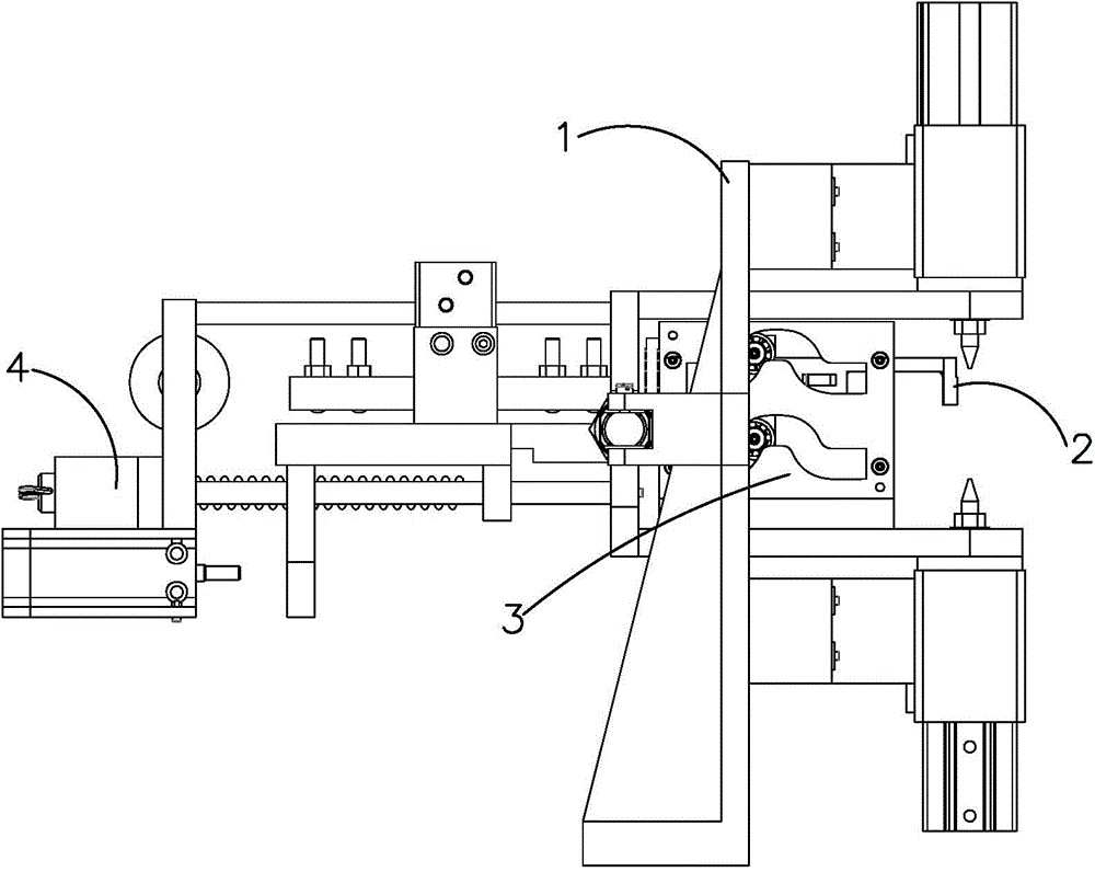
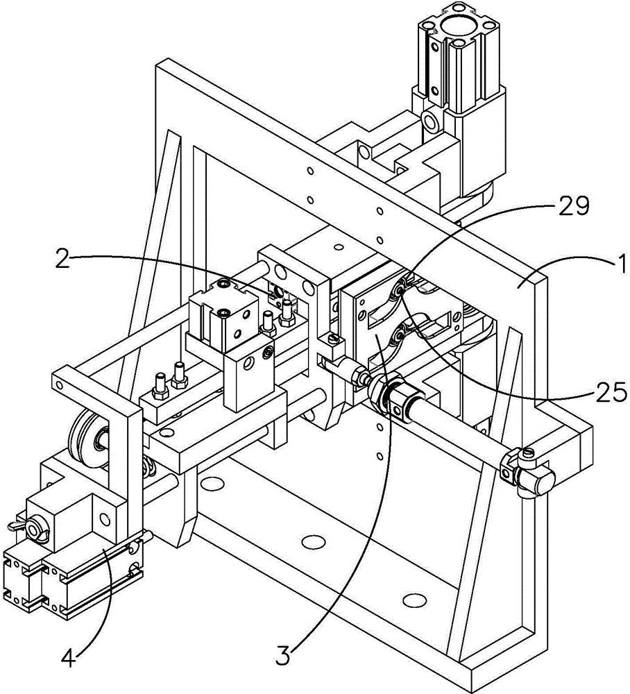
[0019] Such as figure 1 As shown, the present invention discloses a resistance wire feeder, comprising a frame 1, a resistance wire clamping device 2, a guide device 3 and a pushing device 4, the resistance wire clamping device 2 is installed on the guide device 3, and the guide The device 3 is installed on the frame 1 , and the pushing device 4 pushes the resistance wire clamping device 2 to move in the guiding device 3 .

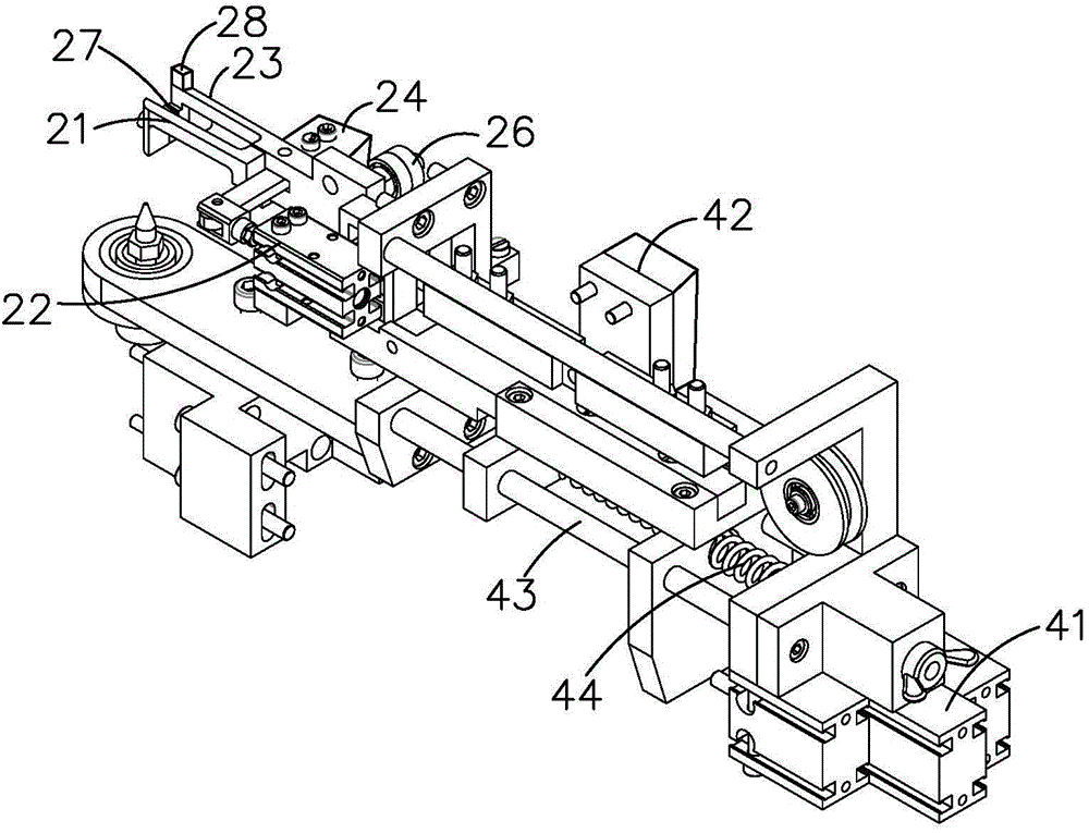
[0020] Such as Figure 1-9 As shown, the resistance wire clamping device 2 is used to pull the resistance wire to move according to the set trajectory and rules, and includes a left clamp 21, a right clamp 23 and a left clamp cylinder 22, and the right clamp 23 and the left clamp The heads 21 are connected by a common rotating shaft 25 to fo...


PUM


Abstract

The invention belongs to the technical field of electronic component manufacturing, and particularly discloses a steady resistance wire clamping device. The steady resistance wire clamping device comprises a left chuck, a right chuck and a left chuck cylinder, the right chuck and the left chunk are connected through one end of a same rotation shaft, the other end of the rotation shaft is provided with a balancing weight, and the weight of the balancing weight is equal to the total weight of the left chunk and the right chunk. Through design of the balancing weight, the stress of the two ends of the rotation shaft is balanced and uniform; when the rotating rotation shaft drives the resistance wire clamping device to move, the resistance wire clamping device is stresses uniformly, and deviation cannot be caused; meanwhile, the stress of the rotation shaft is uniform, and the working life of the device is prolonged.

Description

technical field [0001] The invention belongs to the technical field of manufacturing electronic components, and in particular relates to a steady resistance wire clamping device. Background technique [0002] Resistors, especially wire-wound precision resistors, have the advantages of reliable operation, excellent temperature coefficient of resistance, good stability, no current noise, and no nonlinearity. It has been widely used in weapons and equipment in other fields, and in recent years, a broader application prospect of chip wirewound resistors has emerged. However, due to the limitations of various technical conditions and levels of domestic enterprises, the precision wirewound resistors produced have poor quality stability, low precision, large volume, and poor performance consistency, making it difficult to meet the quality and quantity requirements of military electronic equipment. The resistance winding machine includes a welding machine and a resistance wire feed...

Claims


Application Information

Patent Timeline
IPC IPC(8): H01C17/04
Inventor 冯博玉
Owner CHENGDU HONGTENG TECH
Why Eureka
Try Eureka