Manufacturing method of electric connectors

A technology of an electrical connector and a manufacturing method, which is applied to the manufacturing field of electrical connectors, can solve the problems of assembly difficulty, wear and tear, and poor quality of the electrical connector, and achieves the effects of fast production speed, reduced size and stable quality.

Active Publication Date: 2016-10-05
ACES ELECTRONICS CO LTD
View PDF6 Cites 4 Cited by
  • Summary
  • Abstract
  • Description
  • Claims
  • Application Information

AI Technical Summary

Problems solved by technology

[0003] Commonly used electronic products, such as flash drives, portable hard drives, multimedia storage devices, multimedia audio-visual playback devices, smart phones, tablet computers or notebook computers or desktop computers, etc., are light, thin, short and small. Therefore, all kinds of electronic components used on the circuit board must cooperate with the design of volume reduction. However, the interfaces or electrical connectors used by various electronic products to transmit electronic signals are constantly being developed, improved and innovated. After that, it has a variety of different specifications, such as the Universal Serial Bus (USB), in addition to the original USB2.0 specification, and has continuously innovated and developed the USB3.0 specification, Micro USB2.0, USB3. 0) specifications, Mini Universal Serial Bus (Mini USB2.0, USB3.0) specifications and Universal Serial Bus USB3.1 Type-C specifications, etc., which can be used to cooperate with various peripheral products for electronic signals or data, etc. Transmission, and the electrical connector uses a plurality of terminals to pass through the insulating seat body, and then covers the shielding iron shell on the outside of the insulating seat body, which will lead to more cumbersome processing procedures during manufacturing, and because various parts of the electrical connector are facing The development of light, thin, short, and small design patterns will easily make processing, manufacturing, and subsequent assembly operations more difficult, and will easily cause damage to various small parts, resulting in poor quality of electrical connector products. The failure rate of products also increases, and after a period of use of the formed electrical connector, it will be worn due to the friction between the plastic tongue and the seat of the electrical connector, or due to the plastic tongue, the seat and the shield. The friction between the iron shells will also cause wear and tear, which will affect the reduction of the plugging force of the electrical connector, and it will easily loosen when plugged into each other, and cause many defects such as unstable signal transmission between the terminals of the electrical connector.
[0004] Therefore, how to solve the problems and troubles that the current electrical connectors are easy to cause damage to parts during the process due to their small size, resulting in poor quality of the electrical connectors, and the friction between the plastic parts and metal parts of the electrical connectors is easy The lack and troubles caused by the reduction of plugging force and easy loosening of electrical connectors are the directions that relevant manufacturers in this industry want to study and improve.

Method used


Image

  • Manufacturing method of electric connectors
  • Manufacturing method of electric connectors
  • Manufacturing method of electric connectors

Examples


Embodiment Construction

[0032] In order to achieve the above-mentioned purpose and effect, the technical means adopted in the present invention, its structure, and the method of implementation, etc., are hereby described in detail with respect to the preferred embodiments of the present invention. Its features and functions are as follows, so that it can be fully understood.

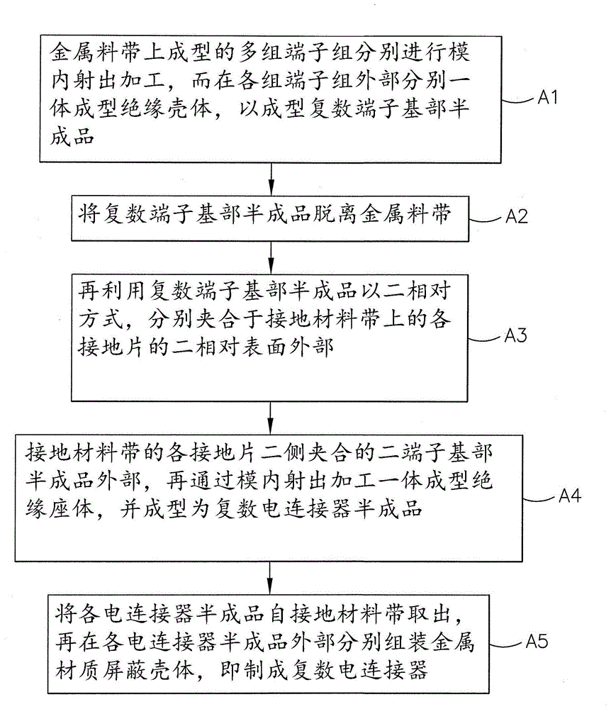
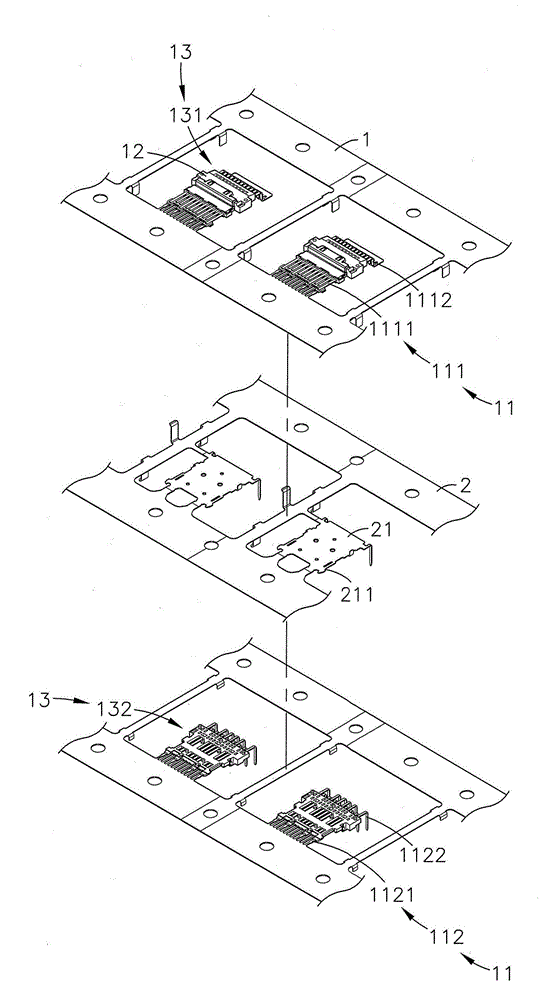
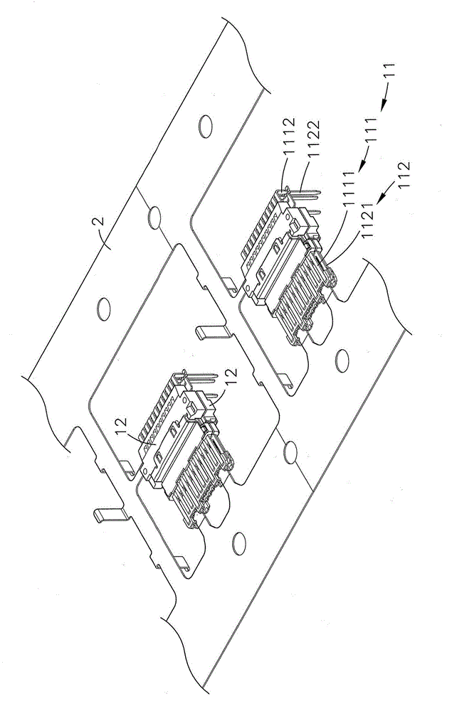
[0033] see figure 1 , figure 2 , image 3 , Figure 4Shown are the flow chart of the present invention, the three-dimensional exploded view of the semi-finished terminal base, the three-dimensional appearance of the semi-finished terminal base, and the three-dimensional appearance of the semi-finished electrical connector. It can be clearly seen from the figures that the electrical connector of the present invention The manufacture method, its step is:

[0034] (A1) Multiple sets of terminal groups 11 formed on the metal strip 1 are respectively subjected to in-mold injection processing (Insert Molding), and an insulating h...


PUM


Abstract

The invention relates to a manufacturing method of electric connectors. The manufacturing method comprises the steps of: carrying out in-mold ejection processing respectively on a plurality of terminal groups formed on a metal strip, forming an insulating housing outside each terminal group in an integrated manner, forming a plurality of terminal base semi-finished products after separation from the metal strip, utilizing two opposite terminal base semi-finished products to clamp the outer parts of two opposite surfaces of each grounding sheet on a grounding material strip, forming an integrated insulating seat body by means of in-mold ejection processing outside the two terminal base semi-finished products clamping each grounding sheet, taking each electric connector semi-finished product out from the grounding material strip out after forming the plurality of electric connector semi-finished products, externally assembling the metal shielding housings, and namely manufacturing a plurality of electric connectors. According to the invention, the purposes of high production speed and stable quality are reached.

Description

technical field [0001] The invention provides a manufacturing method of an electrical connector, especially a manufacturing method that can accelerate the completion of the production process of the electrical connector through an automated process. The terminal base semi-finished products are relatively clamped on the two surfaces of each ground sheet of the ground material belt, and are subjected to in-mold injection processing to achieve the purpose of forming an electrical connector with good quality. Background technique [0002] According to, with the advancement of electronic technology, many electronic and electrical products bring people comfort and convenience in work and life, and also lead people to rely more and more on the use of electronic and electrical products. Through the application of various electronic signals, Operation, control of the operation and execution of electronic and electrical products, and because various electronic and electrical products ...

Claims


Application Information

Patent Timeline
Patent Type & Authority Applications(China)
IPC IPC(8): H01R43/24H01R43/20H01R43/16
Inventor 张君玮吴恭介
Owner ACES ELECTRONICS CO LTD
Why Eureka
Try Eureka