Micro-cultivator transmission mechanism for greenhouse

A technology of transmission mechanism and micro tillage machine, applied in the field of micro tillage machine transmission mechanism and agricultural machinery equipment, can solve the problems of large size, unsuitable for greenhouse planting, high energy consumption, etc., and achieve small size, good cutting efficiency and simple operation Effect

Active Publication Date: 2016-10-12
安徽明亮面业股份有限公司
View PDF7 Cites 2 Cited by
  • Summary
  • Abstract
  • Description
  • Claims
  • Application Information

AI Technical Summary

Problems solved by technology

[0003] Aiming at the above-mentioned deficiencies in the prior art, the main purpose of the present invention is to solve the problems that the current micro-tillers are la

Method used


Image

  • Micro-cultivator transmission mechanism for greenhouse
  • Micro-cultivator transmission mechanism for greenhouse
  • Micro-cultivator transmission mechanism for greenhouse

Examples


Embodiment Construction

[0019] The present invention will be further described below in conjunction with the accompanying drawings and specific embodiments.

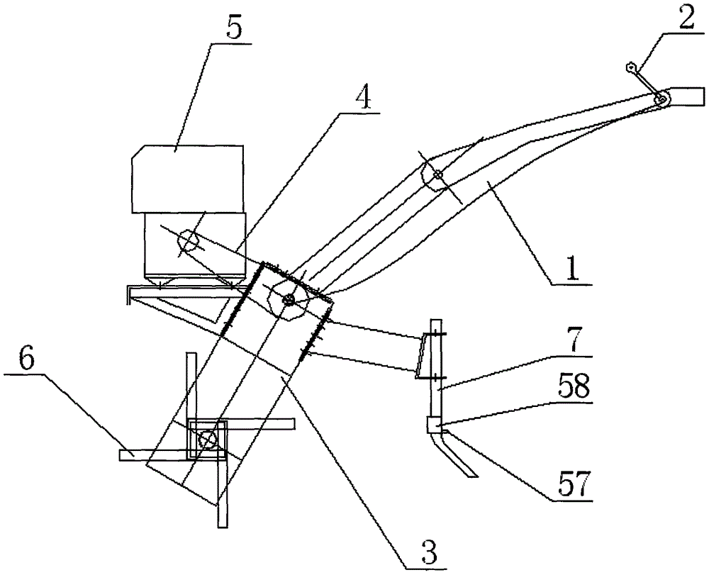
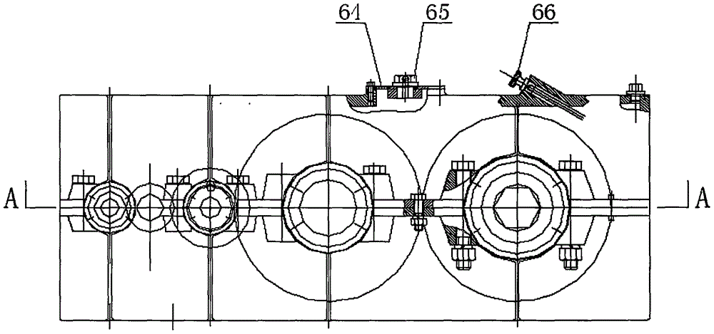
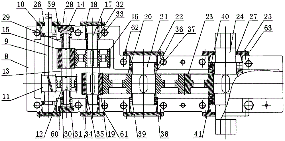
[0020] Such as figure 1 , figure 2 , image 3 , Figure 4 and Figure 5As shown, a micro-cultivator transmission mechanism for a shed according to the present invention includes a clutch assembly 2 installed on the upper end of the handrail 1, and a reducer assembly 3 is installed on the lower end of the handrail 1. The reducer assembly 3 is connected with the engine assembly 5 through the transmission belt 4, a rotary tiller assembly 6 is installed at the lower end of the reducer assembly 3, and a depth-limiting device assembly 7 is also installed on the shell of the reducer assembly 3. The clutch assembly 2, the engine assembly 5 and the depth stop assembly 7 here can adopt the existing mechanical structure, and the innovation of the present invention is that the described reducer assembly 3 includes a casing 8, and the 8 is installed w...


PUM


Abstract

The invention discloses a micro-cultivator transmission mechanism for a greenhouse. The transmission mechanism comprises a clutch assembly installed at the upper end of a handrail and a speed reducer assembly installed at the lower end of the handrail. The speed reducer is connected with an engine assembly through a transmission belt, a rotary tillage cutter assembly is installed at the lower end of the speed reducer assembly, and a depth limiting device assembly is further installed on a shell of the speed reducer assembly. The speed reducer assembly comprises a machine shell, an input shaft is installed in the machine shell, the two ends of the input shaft are rotationally installed in the machine shell through bearings respectively, first bearing end cap assemblies are further installed at the two ends of the input shaft respectively, and one end of the input shaft penetrates through the first bearing end cap assembly of the corresponding side and is connected with the transmission belt. The transmission mechanism is small in size and low in weight; a simpler transmission route is adopted, so the gravity center of a whole micro-cultivator is low, power of the whole micro-cultivator is reduced, an operation mode is simple and direct, and price is low.

Description

technical field [0001] The invention relates to an agricultural mechanical equipment, in particular to a transmission mechanism of a tiller used in a shed, and belongs to the technical field of mechanical equipment. Background technique [0002] Micro tillage machine is specially designed for orchards, vegetable fields, hilly slopes and small plots (water and dry fields) according to the national conditions of our country's vast hills and mountainous areas, small plots, large height differences, and no farming roads. It is powered by a small diesel engine or gasoline engine, and is driven by an integral transmission gearbox or a belt clutch. advanced features. Existing micro tillage machines are mainly used for tillage operations such as paddy fields, dry field plowing, pastoral management, and facility agriculture. Along with the generation of high molecular polymer-polyvinyl chloride, polyethylene, plastic film is widely used in agriculture, and covering small shed and g...

Claims


Application Information

Patent Timeline
IPC IPC(8): A01B33/08
CPCA01B33/082
Inventor 徐涛
Owner 安徽明亮面业股份有限公司
Why Eureka
Try Eureka