
Integrated camera visual vacuum suction device

A negative pressure suction device and negative pressure technology, applied in the field of medical devices, can solve problems such as the complete suction of embryonic tissue that is difficult to clean, prolonged waiting time before surgery, and difficult clinical operations, so as to reduce complexity and workload , convenient suction operation, and the effect of reducing psychological burden

Inactive Publication Date: 2016-10-12
HENAN TUOREN MEDICAL DEVICE GRP
View PDF9 Cites 10 Cited by
  • Summary
  • Abstract
  • Description
  • Claims
  • Application Information

AI Technical Summary

Problems solved by technology

[0002] The currently used disposable uterine suction tube cannot observe the specific situation in the uterus, and can only rely on the doctor's clinical experience, so there are disadvantages of blind operation of uterine suction, large trauma, and it is easy to cause infection and complications. It brings a lot of pain; in addition, due to the blind operation of the operation, the doctor used to touch the catheter to find the embryo, and had to wait for the embryo to grow to a certain size before performing the operation, which greatly prolonged the waiting time for the patient before the operation; the traditional general-purpose negative pressure suction The tube is mostly a simple hollow metal tube. There is a suction port on the top side of the metal tube, and a negative pressure suction tube and a negative pressure bottle are connected to the end of the metal tube. The operation method of the negative pressure suction tube in this way is mostly blind operation. The embryonic tissue cannot be directly observed, and it cannot be operated under visible conditions. The success rate of suction is not high, and sometimes it is not easy to completely aspirate the embryonic tissue. The clinical operation is difficult, takes a long time, and is likely to cause cross-infection. cause pain and harm

Method used


Image

  • Integrated camera visual vacuum suction device

Examples


Embodiment 1

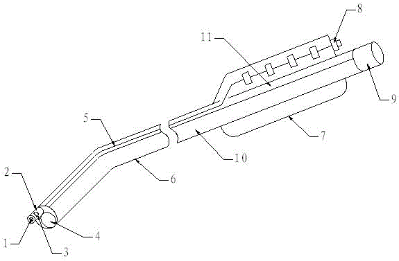
[0014] Such as figure 1 As shown, a kind of integrated camera-visible negative pressure suction device, it comprises double cavity suction tube 6, and described double cavity suction tube 6 is internally provided with negative pressure suction cavity 10 and side cavity 11, and described negative pressure suction cavity The head end of 10 is provided with negative pressure suction port 4, is provided with signal wire 5 in described side chamber 11, and the head end of described side chamber 11 is connected with miniature camera 2, and described signal wire 5 and miniature camera 2 connection, the front end of the micro-camera 2 is provided with a feathering lens 1, the front end of the micro-camera 2 is also provided with an LED patch lamp 3, the tail of the double-chamber suction tube 6 is provided with a handle 7, and the dual-chamber The tail end of the suction tube 6 is provided with a negative pressure connector 9 , the tail end of the signal line 5 is connected with a vid...

Embodiment 2

[0017] Such as figure 1 As shown, a kind of integrated camera-visible negative pressure suction device, it comprises double cavity suction tube 6, and described double cavity suction tube 6 is internally provided with negative pressure suction cavity 10 and side cavity 11, and described negative pressure suction cavity The head end of 10 is provided with negative pressure suction port 4, is provided with signal wire 5 in described side chamber 11, and the head end of described side chamber 11 is connected with miniature camera 2, and described signal wire 5 and miniature camera 2 connection, the front end of the micro-camera 2 is provided with a feathering lens 1, the front end of the micro-camera 2 is also provided with an LED patch lamp 3, the tail of the double-chamber suction tube 6 is provided with a handle 7, and the dual-chamber The tail end of the suction tube 6 is provided with a negative pressure connector 9 , the tail end of the signal line 5 is connected with a vid...


PUM


Abstract

The invention relates to an integrated camera visual vacuum suction device, which comprises a double-cavity suction tube, wherein a vacuum suction cavity and a lateral cavity are arranged inside the double-cavity suction tube; the head end of the vacuum suction cavity is provided with a vacuum suction opening; a signal wire is arranged in the lateral cavity; the head end of the lateral cavity is connected with a miniature camera; the signal wire is connected with the miniature camera; the front end of the miniature camera is provided with an eclosion lens; the front end of the miniature camera is also provided with an LED (light emitting diode) patch lamp; the tail part of the double-cavity suction tube is provided with a handle; the tail end of the double-cavity suction tube is provided with a negative pressure connecting head; the tail end of the signal wire is connected with a video connector; the video connector is arranged at the tail end of the handle. The integrated camera visual vacuum suction device has the advantages that the structure is reasonable; the operation is fast; light weight and flexibility are realized; the success rate is high; the safety is high; the work intensity of physicians is effectively reduced; the injury on human body tissues is reduced.

Description

technical field [0001] The invention belongs to the technical field of medical devices, and in particular relates to an integrated camera-visible negative pressure suction device, in particular to a device that can easily and quickly observe video images of positions to be sucked and tissue fluids during operations and daily care. Integrated camera visual vacuum suction device. Background technique [0002] The currently used disposable uterine suction tube cannot observe the specific situation in the uterus, and can only rely on the doctor's clinical experience, so there are disadvantages of blind operation of uterine suction, large trauma, and it is easy to cause infection and complications. It brings a lot of pain; in addition, due to the blind operation of the operation, the doctor used to touch the catheter to find the embryo, and had to wait for the embryo to grow to a certain size before performing the operation, which greatly prolonged the waiting time for the patien...

Claims


Application Information

Patent Timeline
Patent Type & Authority Applications(China)
IPC IPC(8): A61M1/00A61B17/42
CPCA61B17/42A61M2202/0494A61M2202/09A61M2210/1433A61M1/73A61M2202/0014
Inventor 卢志增程志磊牛富超杨勇苗威
Owner HENAN TUOREN MEDICAL DEVICE GRP
Learn More