Adjustable intelligent charging and discharging mechanism of punch press

An intelligent punching and adjustable technology, applied in metal processing equipment, feeding devices, manufacturing tools, etc., can solve the problems of improper coordination between the feeding mechanism and the manipulator, increase production and processing costs, and occupy a long time for machine tools. The effect of good rhythm, improved efficiency and simple structure

Active Publication Date: 2016-10-12
江苏迈步智能装备科技有限公司
View PDF9 Cites 5 Cited by
  • Summary
  • Abstract
  • Description
  • Claims
  • Application Information

AI Technical Summary

Problems solved by technology

The technical solution proposes to set the X-axis slide rail and the Z-axis mechanical arm slidingly connected on the X-axis slide rail. Although the X and Z dimensions are set, the X-axis is only equipped with a slide rail, and the Z-axis is only provided with a mechanical arm. Although it solves the problem that the loading and unloading mechanism and structure will cause the loading and unloading work to take up a long time on the machine tool, and the loading and unloading action time will be misaligned with the machine tool processing time, which will increase the production and processing costs, but there are still loading mechanisms and manipulators. In the case of inappropriate cooperation, it is necessary to manually adjust the stroke of the manipulator to achieve continuous work.

Method used


Image

  • Adjustable intelligent charging and discharging mechanism of punch press
  • Adjustable intelligent charging and discharging mechanism of punch press
  • Adjustable intelligent charging and discharging mechanism of punch press

Examples


Embodiment Construction

[0026] The present invention will be described in further detail below in conjunction with the accompanying drawings and embodiments. It should be understood that the specific embodiments described here are only used to explain the present invention, not to limit the present invention.

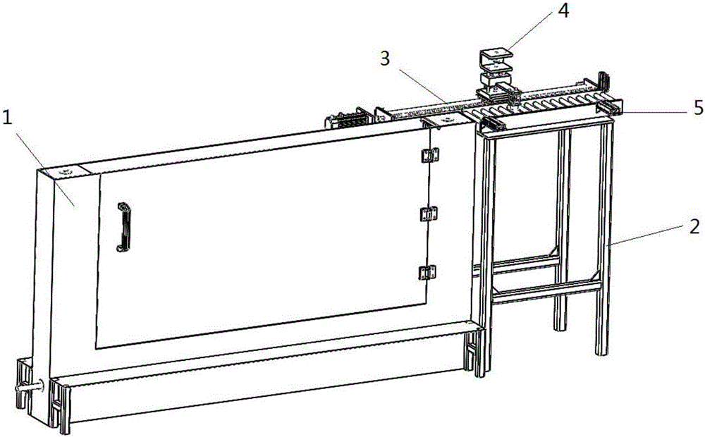
[0027] The invention discloses an adjustable intelligent punching and unloading mechanism, which is installed at the loading position of the machine tool, such as figure 1Shown: including feeding mechanism 1, feeding mechanism 2, X-axis left and right moving linear module 3 and Z-axis moving up and down linear module 4; the feeding mechanism 1 is installed on one side of the machine tool, and the feeding mechanism 2 is erected on the On the mechanism 1, a linear module 3 for moving the X-axis left and right and a linear module 4 for moving the Z-axis up and down are respectively installed above the feeding mechanism 2. Further preferably, the feeding mechanism 1 and the feeding mechanism 2 ar...


PUM


Abstract

The invention provides an adjustable intelligent charging and discharging mechanism of a punch press. The adjustable intelligent charging and discharging mechanism is mounted at a charging position of a machine tool, and comprises a charging mechanism, a feeding mechanism, an X-axis left-and-right movement liner die set, and a Z-axis up-and-down movement liner die set, wherein the charging mechanism is mounted on one side of the machine tool; the feeding mechanism is erected on the charging mechanism, and the X-axis left-and-right movement liner die set, and the Z-axis up-and-down movement liner die set are mounted on the feeding mechanism. The adjustable intelligent charging and discharging mechanism of the punch press comprises the charging mechanism, the feeding mechanism, the X-axis left-and-right movement liner die set, and the Z-axis up-and-down movement liner die set, and through the X-axis left-and-right two-dimensional movement liner die set, and the Z-axis up-and-down two-dimensional movement liner die set, rapid and intelligent material taking can be realized. The adjustable intelligent charging and discharging mechanism is simple in structure and high in operating stability, the precision of a manipulator is high, and the consistency of products is notably improved; besides, normal time for charging and discharging needs to be four hours or above, and the normal processing time of the adjustable intelligent charging and discharging mechanism disclosed by the invention is within 2 hours, so that the efficiency is doubled.

Description

technical field [0001] The invention relates to the technical field of electrical automation, in particular to an adjustable intelligent punching and unloading mechanism. Background technique [0002] An important feature of intelligent punching and unloading is that it has a high degree of automation and continuous production. To achieve continuous feeding production, the material is continuously loaded through the feeding mechanism. If the feeding mechanism and the manipulator do not cooperate properly, the manipulator cannot suck the material. It will cause the assembly line to stop working and continuous processing cannot be realized. Usually, when the feeding machine and the manipulator do not cooperate properly, it is necessary to manually adjust the stroke of the manipulator to achieve continuous work. [0003] For example, Chinese patent CN205147331U discloses an automatic loading and unloading lathe, which is characterized in that: the lathe is a numerical control d...

Claims


Application Information

Patent Timeline
Patent Type & Authority Applications(China)
IPC IPC(8): B21D43/18
CPCB21D43/18
Inventor 龚勋申晓荣杨建锋缪杨琴
Owner 江苏迈步智能装备科技有限公司
Why Eureka
Try Eureka