
A multifunctional laser cutting machine

A laser cutting machine and multi-functional technology, applied in laser welding equipment, cleaning methods using tools, manufacturing tools, etc., can solve the problems that affect the processing efficiency of laser cutting machines, lack of protective covers for laser heads, and easy dust ingress of laser heads, etc. , to achieve the effect of reducing human labor, improving cleaning efficiency and smooth movement

Inactive Publication Date: 2018-09-28
CHENGDU MATSUKAWA METAL MATERIALS
View PDF5 Cites 0 Cited by
  • Summary
  • Abstract
  • Description
  • Claims
  • Application Information

AI Technical Summary

Problems solved by technology

[0004] The purpose of the present invention is to provide a multifunctional laser cutting machine to achieve the purpose of setting a protective cover outside the laser head and automatically cleaning the accumulated dust on the laser head regularly to increase the service life of the laser head and increase the safety of the laser head The purpose is to solve the problem that the laser head of the existing laser cutting machine lacks a protective cover, the laser head is easy to enter dust, is corroded and has low safety, and the accumulation of a large amount of dust on the laser head affects the processing efficiency of the laser cutting machine

Method used


Image

  • A multifunctional laser cutting machine
  • A multifunctional laser cutting machine
  • A multifunctional laser cutting machine

Examples


Embodiment Construction

[0021] The present invention will be described in further detail below through specific implementation examples and in conjunction with the accompanying drawings.

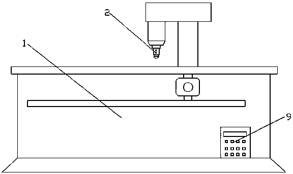
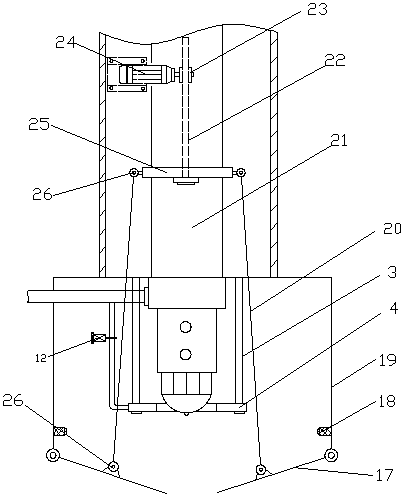
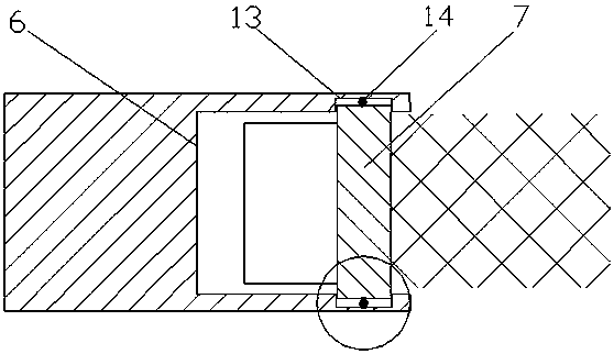
[0022] figure 1 , figure 2 , image 3 , Figure 4 and Figure 5 It shows a structural schematic diagram of a laser head cleaning device for a laser cutting machine, which is characterized in that it includes a body 1, a laser head 2 located on the body 1, and a push rod 21 for driving the laser head 2 up and down. The push rod 21 Drive the laser head 2 to adjust its working position in the vertical direction. The outside of the laser head 2 is covered with a protective cover 19 with an open end, and the protective cover 19 passes through the laser head 2 and is fixedly connected to the body 1. , the laser head 2 can move up and down in the protective cover body 19, one end of the protective cover body 19 is fixedly connected with the body 1, and the other end of the protective cover body 19 is hinged with two ...


PUM


Abstract

The invention discloses a multi-functional laser cutter and belongs to the technical field of laser cutters. The multi-functional laser cutter comprises a machine body, a laser head and a push rod, wherein the laser head is positioned on the machine body; the push rod is used for driving the laser head to move up and down; the laser head is externally covered by a protective cover body of which the two ends are opened; the other end of the protective cover body is articulated with two same sealing plates; the two sealing plates are matched with the end openings of the protective cover body after being spliced; a transmission rod is arranged between a sliding ring and each sealing plate; the two ends of each transmission rod are respectively articulated with the sliding ring and the corresponding sealing plate; the multi-functional laser cutter also comprises a supporting frame which is arranged outside the laser head; the supporting frame is provided with a top plate; a through hole matched with the laser head is formed in the corresponding position of the top plate; a cleaning roller matched with the through hole is rotationally arranged inside an annular groove; an air passage is formed between the outer circle surface of the cleaning roller and the annular groove; a cleaning hairbrush is arranged on the inner circle surface of the cleaning roller. The multi-functional laser cutter disclosed by the invention is capable of solving the problems that the laser head cannot be protected and dust cannot be automatically cleared.

Description

technical field [0001] The present invention relates to the technical field of laser cutting machines, in particular to a multifunctional laser cutting machine. Background technique [0002] Laser cutting is to focus the laser emitted from the laser into a high power density laser beam through the optical path system. The laser beam irradiates the surface of the workpiece to make the workpiece reach the melting point or boiling point, and at the same time, the high-pressure gas coaxial with the beam blows away the molten or vaporized metal. With the movement of the relative position of the beam and the workpiece, the material finally forms a slit, so as to achieve the purpose of cutting. The laser emitting head of the existing laser cutting machine is exposed on the outside of the fuselage when it is not working, without any interference. The protection device of the laser head, the laser head is easy to accumulate dust and is affected by the corrosion of the surrounding en...

Claims


Application Information

Patent Timeline
Patent Type & Authority Patents(China)
IPC IPC(8): B08B1/04B23K26/38B23K26/08B23K26/14B23K26/70
CPCB23K26/14B23K26/38B23K26/70B23K26/706
Inventor 周建川
Owner CHENGDU MATSUKAWA METAL MATERIALS
Learn More