
Automatic control method and system of electric tool

An automatic control system and power tool technology, applied in the direction of power tools, manufacturing tools, etc., can solve the problems of increasing the complexity of hardware and software design, low intelligence, and difficult to stop the number of laps, and achieve after-sales processing and maintenance. , The effect of high intelligence and convenient after-sales processing

Active Publication Date: 2016-10-12
杭州势垒科技有限公司
View PDF6 Cites 3 Cited by
  • Summary
  • Abstract
  • Description
  • Claims
  • Application Information

AI Technical Summary

Problems solved by technology

For example, during high-altitude operations, if the electric wrench cannot be stopped before it falls off during screwing, the nuts will easily fly out, and falling objects will have a great impact on personnel safety.
[0004] 2. There are other existing implementation methods, which judge whether to loosen the nut by the current threshold or the linear change rate of the current drop, or by the motor speed threshold or the speed rise rate, etc., plus the previous load situation; this method is easy to cause misjudgment , such as the current sampling signal is disturbed, or the load suddenly drops due to improper use by the user, and because the load judgment requires a certain filtering delay, it is not easy to obtain an accurate number of stop turns
[0005] 3. Existing judgment methods mostly use current sampling to judge the load, and the one-way change of the load to determine the state of the nut loosening. However, during the actual operation of the motor, due to the existence of the speed regulation mechanism and the motor feedback, the instantaneous current value is always constant. Changes often require analog or digital filtering to obtain reliable sampling, which greatly increases the complexity of hardware and software design;
[0006] 4. The existing mode cannot obtain the current and long-term load working status of the electric tool, the degree of intelligence is low, and it is inconvenient to use

Method used

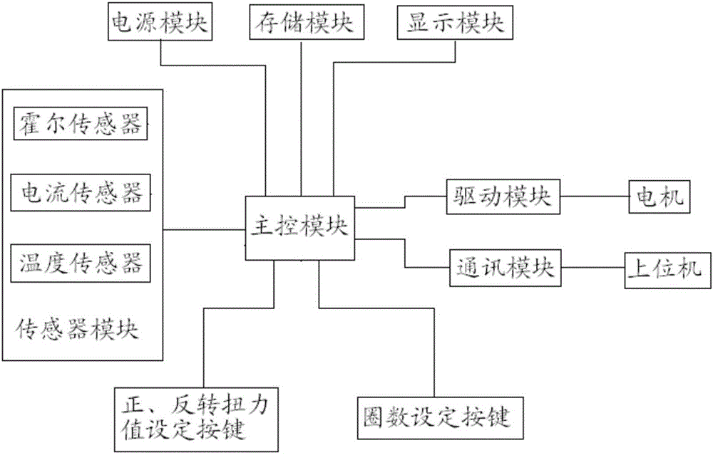
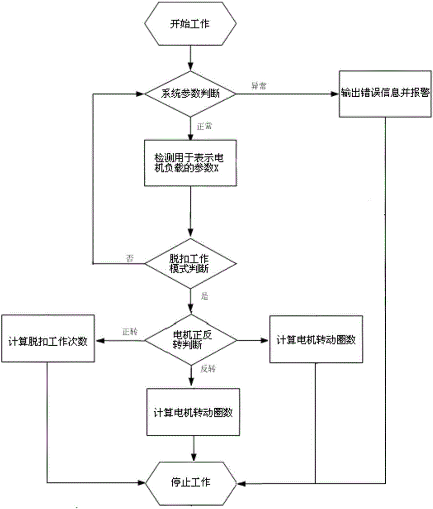
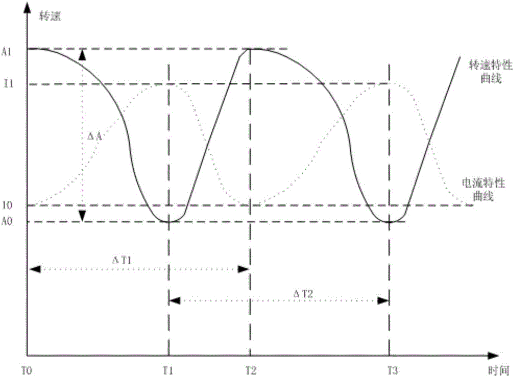

Image

  • Automatic control method and system of electric tool
  • Automatic control method and system of electric tool
  • Automatic control method and system of electric tool

Examples


Embodiment Construction

[0029] The technical solutions of the present invention will be further described below in conjunction with the accompanying drawings, but the present invention is not limited to these embodiments.

[0030] When the electric tool is tightening or loosening the screw, due to the large external load blocking the rotation of the connecting component, it will cause the torsion spring to deform and produce periodic stress release. The stress is output to the load through the spring pushing the impact block. This process is electric The tripping mode of operation of the tool.

[0031] When the power tool enters the tripping mode, due to the different degrees of deformation of the torsion spring, the corresponding stresses are different. The greater the deformation of the torsion spring, the stronger the stress, the greater the corresponding motor load, the lower the motor speed, and the greater the circuit current. After the torsion spring reaches the deformation limit, the stress i...


PUM


Abstract

The invention relates to the field of electric field and particularly relates to an automatic control method and system of an electric tool. The control method comprises the following steps: detecting a parameter X for representing a motor load; judging a releasing work mode of the electric tool according to the parameter X; judging forward and backward rotation of the motor; and generating a corresponding control signal to further control the motor to work according to judgment of the releasing work mode of the electric tool and the forward and backward rotation of the motor. Through judgment of the releasing work mode of the electric tool and the forward and backward rotation of the motor, the degree of a screw needed to be fastened or loosened is further controlled, so that the electric tool is intelligently, conveniently and safely used; when a releasing part reaches the releasing number of times, damageable parts are reminded to be replaced, so that the electric tool is conveniently and safely used; through the load work and the releasing work number of times stored by the electric tool, information of working hour of the device can be known, so that after-sale treatment and maintenance are facilitated.

Description

technical field [0001] The invention relates to the field of electric tools, in particular to an automatic control method and system for electric tools. Background technique [0002] The current electric tools have the following problems in the process of loosening fasteners: [0003] 1. Due to the high speed, it is difficult to control the degree of loosening the fasteners. For example, it cannot be stopped after a few turns of loosening, or a few turns before the bolt falls off. For example, during high-altitude operations, if the electric wrench cannot be stopped before it falls off during screwing, the nuts will easily fly out, and falling objects will have a great impact on personnel safety. [0004] 2. There are other existing implementation methods, which judge whether to loosen the nut by the current threshold or the linear change rate of the current drop, or by the motor speed threshold or the speed rise rate, etc., plus the previous load situation; this method is...

Claims


Application Information

Patent Timeline
IPC IPC(8): B25B21/00
CPCB25B21/00
Inventor 曾华周冬
Owner 杭州势垒科技有限公司
Learn More