A Double Row Radial Piston Hydraulic Retarder with Two End Face Discs

A retarder and distribution plate technology, applied in the direction of brakes, etc., can solve the problems of waste of heat energy consumption, kinetic energy loss, and high installation complexity, and achieve the effect of strong continuous working ability, recycling and high space utilization.

Active Publication Date: 2018-10-19
XI AN JIAOTONG UNIV
View PDF4 Cites 0 Cited by
  • Summary
  • Abstract
  • Description
  • Claims
  • Application Information

AI Technical Summary

Problems solved by technology

[0002] At present, there are mainly two kinds of automobile retarders on the market: hydraulic retarder and electric eddy current retarder. The hydraulic retarder drives the liquid to rotate through the rotation of the rotor connected to the transmission shaft, so that the kinetic energy of the liquid is increased. Then impact the vane on the upper end of the stator, causing the loss of kinetic energy and converting it into heat energy to consume the kinetic energy of the car, thus playing a braking role. However, the hydraulic retarder is generally installed at the output end of the gearbox, which makes its installation more complicated. Moreover, the purchase cost is also high; while the eddy current retarder is a device that uses the principle of electromagnetism to convert the kinetic energy of the car into heat energy and dissipate it, thereby achieving deceleration and braking. However, the weight of the eddy current retarder is large. The heat dissipation ability is poor, and the continuous working ability is relatively low. During use and maintenance, it is necessary to adjust the air gap, check the shaft seal, output shaft seal ring, fastening bolts, etc., resulting in high maintenance costs.
At the same time, it can be seen that both of these two retarders convert the kinetic energy of the car when braking into heat energy and waste it when they are working, and the braking energy has not been effectively recycled.

Method used


Image

  • A Double Row Radial Piston Hydraulic Retarder with Two End Face Discs
  • A Double Row Radial Piston Hydraulic Retarder with Two End Face Discs
  • A Double Row Radial Piston Hydraulic Retarder with Two End Face Discs

Examples


Embodiment Construction

[0032] The present invention will be described in detail below in conjunction with the accompanying drawings.

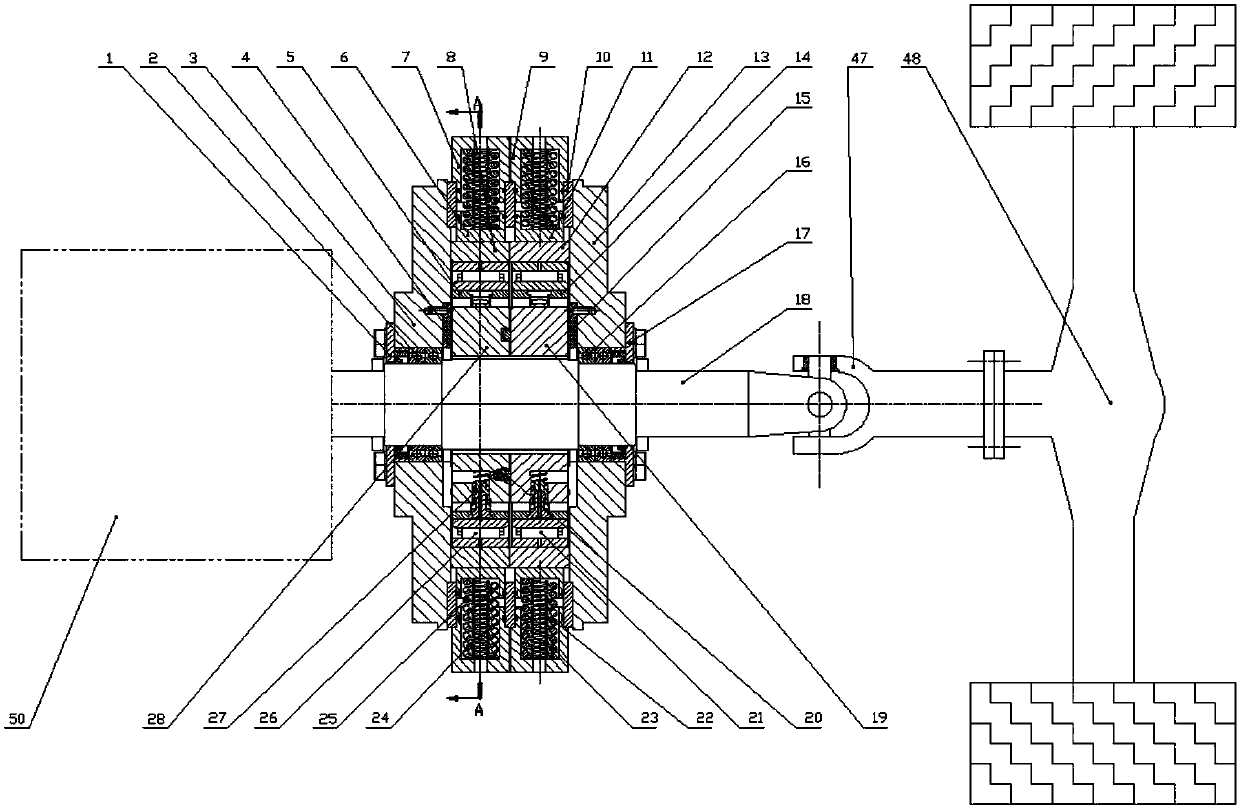
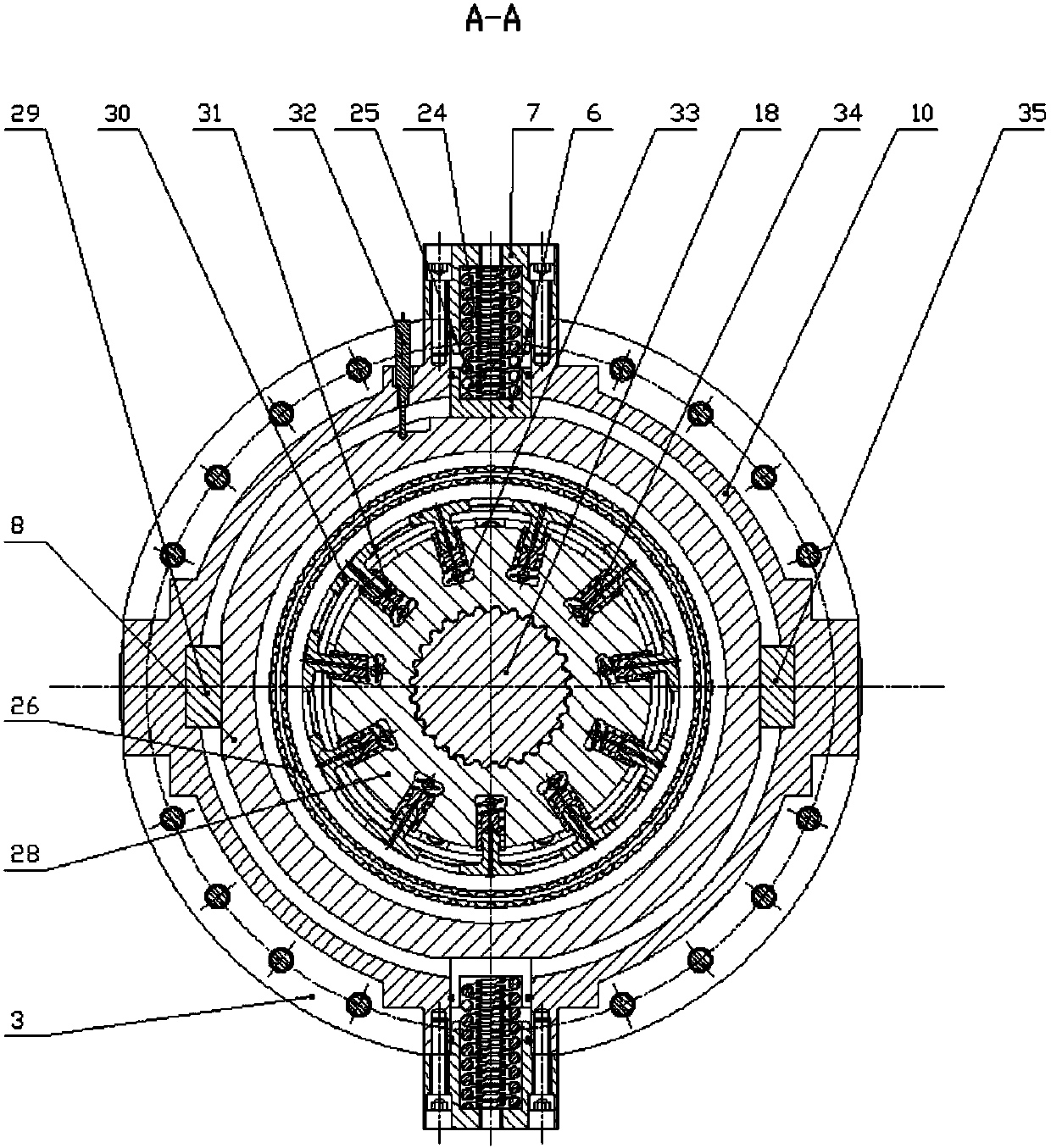
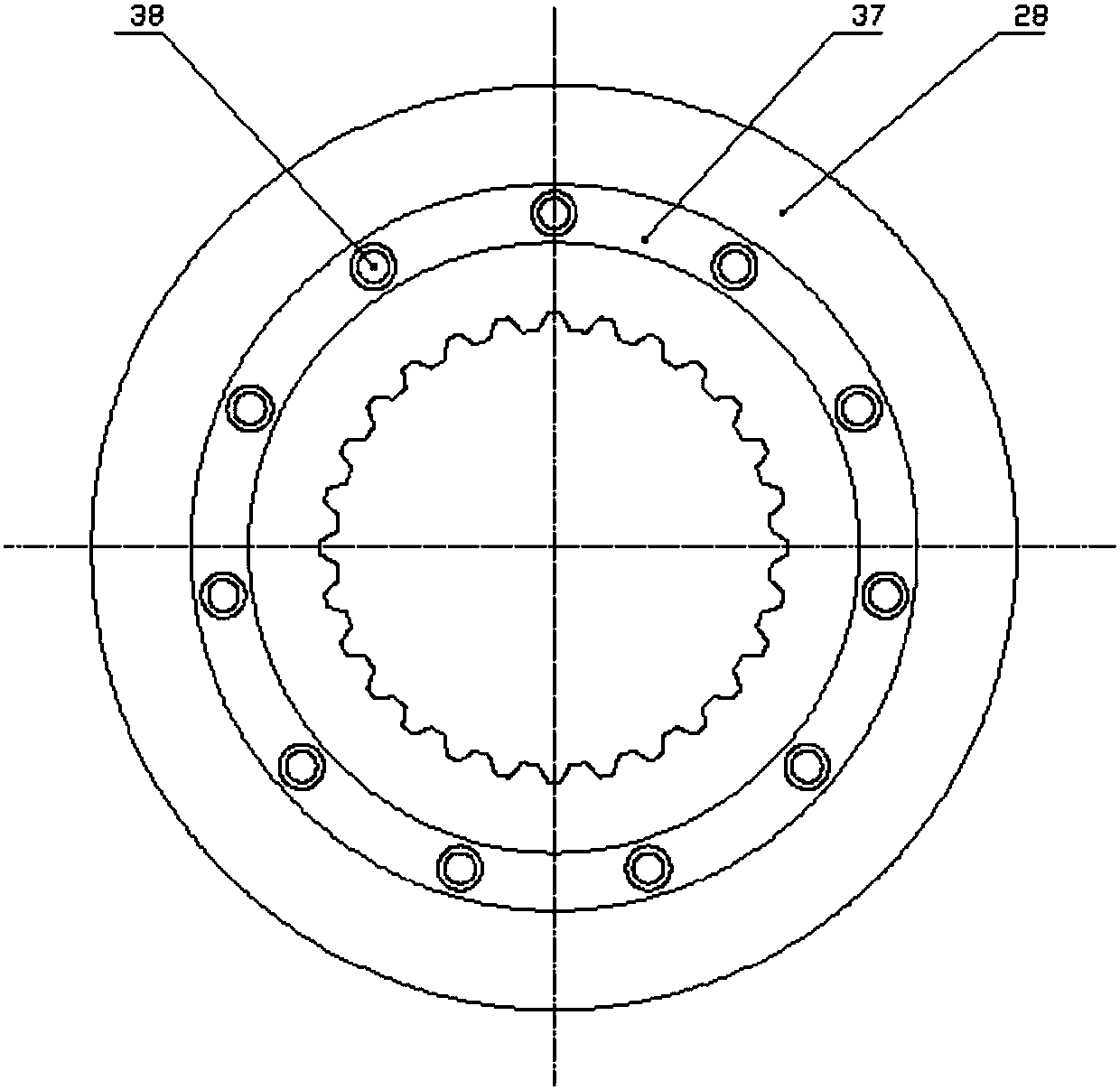
[0033] refer to figure 1 , figure 2 , image 3 , Figure 5, a double-row radial plunger hydraulic retarder with two end face distribution plates, including a transmission shaft 18, the front end of the transmission shaft 18 is connected to the gearbox 50, and the rear end of the transmission shaft 18 is connected to the drive axle through a universal joint 47 48 connection, the first cylinder 28 and the second cylinder 19 are installed side by side in the middle of the transmission shaft 18, and are connected with the transmission shaft 18 through a spline, and the first cylinder 28 is opened on the side opposite to the second cylinder 19. There is an annular groove 37, and the cylinder middle ring 20 is installed in the annular groove 37 and pressed against the second cylinder 19, and a row of diameters are parallelly opened on the outer circumferences of the fi...


PUM


Abstract

A double-row radial plunger hydraulic retarder with two end face distribution plates, including a transmission shaft, the front end of the transmission shaft is connected with the gearbox, the rear end is connected with the drive axle, and two cylinders are installed side by side in the middle of the transmission shaft One cylinder has an annular groove and is equipped with an intermediate ring of the cylinder. A row of radial plunger holes are respectively opened in parallel on the outer circumference of the two cylinders. Between each plunger hole and the plunger Equipped with a return spring, the top of the sliding shoe installed on the plunger is pressed against the inner ring of the needle roller bearing fixed on the stator. The upper and lower sides of the stator are pressed by two variable pistons, and the left and right sides are pressed by friction blocks. Compression and positioning are carried out through the left end cover of the retarder and the right end cover of the retarder, the variable piston is installed in the middle housing, and the two cylinders are respectively pressed against the flow plate installed on the left and right end covers of the retarder. Recycling of kinetic energy during braking, compact overall structure, stable operation, no axial force, and automatic hydraulic compensation.

Description

technical field [0001] The invention belongs to the technical field of automobile retarders, and in particular relates to a double-row radial plunger hydraulic retarder with two end face distribution plates. Background technique [0002] At present, there are mainly two kinds of automobile retarders on the market: hydraulic retarder and electric eddy current retarder. The hydraulic retarder drives the liquid to rotate through the rotation of the rotor connected to the transmission shaft, so that the kinetic energy of the liquid is increased. Then impact the vane on the upper end of the stator, causing the loss of kinetic energy and converting it into heat energy to consume the kinetic energy of the car, thus playing a braking role. However, the hydraulic retarder is generally installed at the output end of the gearbox, which makes its installation more complicated. Moreover, the purchase cost is also high; while the eddy current retarder is a device that uses the principle o...

Claims


Application Information

Patent Timeline
Patent Type & Authority Patents(China)
IPC IPC(8): B60T10/00
CPCB60T10/00
Inventor 赵升吨杨红伟杨元元杨雪松张以升钟玮
Owner XI AN JIAOTONG UNIV
Why Eureka
Try Eureka