
Multifunctional all-terrain special vehicle

An all-terrain, special vehicle technology, applied in motor vehicles, transportation and packaging, etc., can solve the problems of inability to change the wheel spacing and ground clearance, energy consumption and fuel consumption, and high wind resistance coefficient, so as to improve the land passing capacity and reduce the number of vehicles. Body weight, the effect of improving propulsion efficiency

Active Publication Date: 2016-10-12
丁赫
View PDF6 Cites 8 Cited by
  • Summary
  • Abstract
  • Description
  • Claims
  • Application Information

AI Technical Summary

Problems solved by technology

[0005] 1. The screw cylinder of the screw propulsion vehicle cannot reduce the weight, so it consumes energy and oil
[0006] 2. The amphibious screw-propelled vehicle cannot float or sink because it relies on the buoyancy of the hollow buoy to pass through the water, and the propulsion efficiency is low
[0007] 3. The screw-propelled vehicle cannot change the distance between the wheels and the ground clearance, and cannot drive in a narrow space. It has a high drag coefficient on a flat road, and its ability to overcome obstacles is not significantly enhanced compared with wheeled vehicles.

Method used


Image

  • Multifunctional all-terrain special vehicle
  • Multifunctional all-terrain special vehicle
  • Multifunctional all-terrain special vehicle

Examples


Embodiment Construction

[0038] The present invention will be described in further detail below in conjunction with the accompanying drawings.

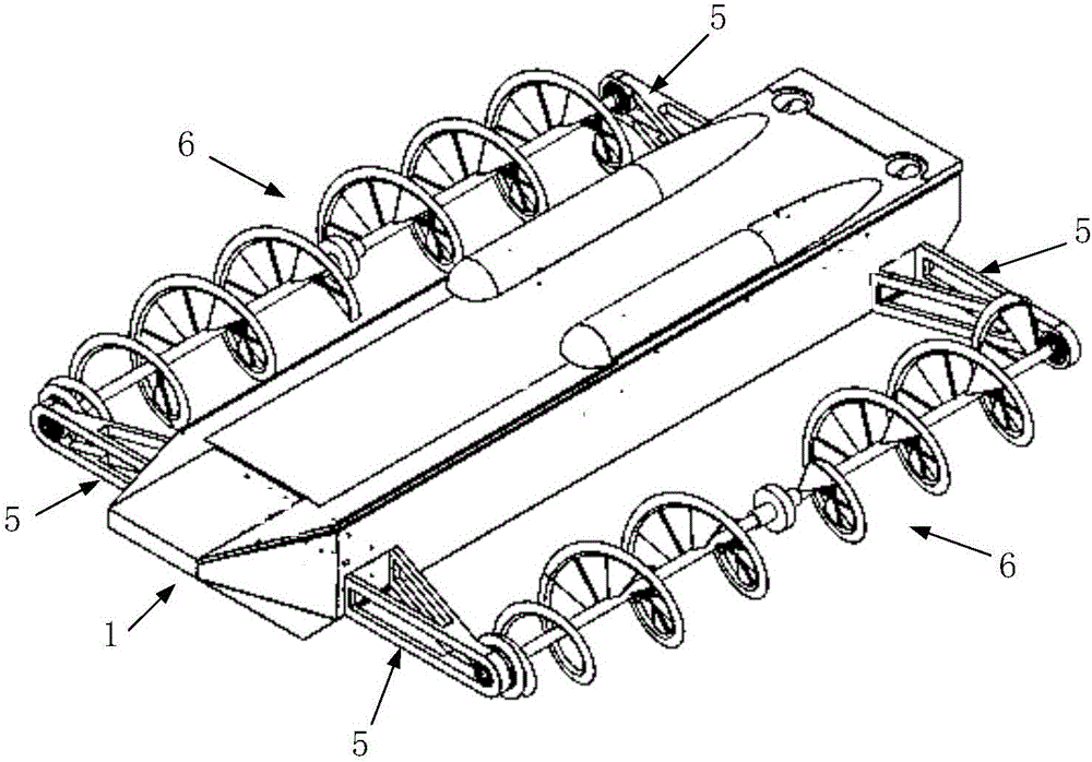
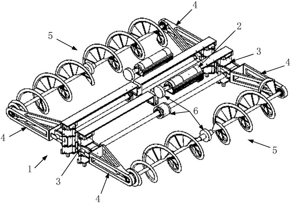
[0039] The multifunctional all-terrain special vehicle of the present invention comprises a car body 1, a power drive device 2, a cantilever drive device 3, a cantilever 4, a wheel assembly 5 and a transmission device 6, such as figure 1 , figure 2 shown.

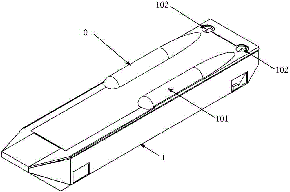
[0040] The car body 1 is a ship-like polyhedron shell, the bottom of which draws on the shape characteristics of the ship hull, and has the ability to move forward stably in water and to cover obstacles on land, such as image 3 As shown, the rear part of the car body 1 is located on both sides of the upper surface, and a shuttle-shaped engine fairing 101 is arranged along the axial direction of the casing to reduce the drag coefficient and improve the heat dissipation capacity of the engine inside the car body 1. At the same time, an L-shaped impeller drainage channel 102 is designed at the inner rear ...


PUM


Abstract

The invention discloses a multifunctional all-terrain special vehicle. The multifunctional all-terrain special vehicle comprises a vehicle body, wheel assemblies, power driving devices, and transmission devices, wherein the wheel assemblies are mounted on the two sides of the vehicle body; power is provided by the power driving devices, and is transmitted to the wheel assemblies by the transmission devices; each of the wheel assemblies comprises a wheel shaft and two hubs; two ends of each of the wheel shafts are mounted at the top ends of two cantilevers through bearings; the bottom ends of the two cantilevers are connected with cantilever driving devices mounted in the vehicle body, and the cantilevers are driven to swing up and down by the cantilever driving devices; an outer ring of each of the two hubs adopts a spiral line structure and sleeves the corresponding wheel shaft, besides, an outer edge of each of the outer rings is designed into a cutting edge shape, and an inner ring of each of the hubs is designed into an embedded blade. The multifunctional all-terrain special vehicle disclosed by the invention can be applied to the fields of military wars, emergency rescue and disaster relief, polar investigation, civilian driving and the like, has the functions of enabling the height of a chassis to be changed, enabling the distance between the wheel shafts to be changed, climbing hills, surmounting obstacles, travelling in water and on land and the like, and can be used for performing detection and operation in places with complex terrains and extreme environments, such as rock and soil, desert, ice surfaces, snowfields, swamps, and deep water.

Description

technical field [0001] The invention belongs to the field of multifunctional special vehicles, in particular to a multifunctional all-terrain special vehicle with a unique vehicle body and tire structure. Background technique [0002] The spiral propulsion vehicle was first proposed by the American inventor Jacob Morath in 1868. In 1907, Americans James and Ira Peavey manufactured the first spiral propulsion vehicle. Special vehicle for driving on harsh terrain. But because this kind of vehicle wheel mass is big, causes fuel consumption big, and can not run on flat road surface, therefore fails to be popularized. Screw-propelled vehicles have only been used in a few areas so far. [0003] The continuous propulsion method was originally proposed by the British inventor Richard Love. In 1868, American inventor Jacob Morath designed the prototype of this solution: a vehicle using a screw propulsion. Of course, it was not recognized by others at the time. In 1907, Americans...

Claims


Application Information

Patent Timeline
IPC IPC(8): B62D57/036
CPCB62D57/036
Inventor 丁赫
Owner 丁赫
Learn More