Centrifugal gear shifting device

A technology for shifting devices and shifting parts, which is applied in transportation and packaging, bicycle gear transmission mechanisms, bicycle accessories, etc., and can solve problems such as the inability to realize overrunning clutches and shifting at the same time, the inability to realize automatic shifting, and the difficulty of maintenance by workers. problems, to achieve the effect of compact structure, reliable shifting and convenient operation

Active Publication Date: 2016-10-12
ZHANGJIAGANG CHUANJUN VEHICLE IND CO LTD
View PDF5 Cites 11 Cited by
  • Summary
  • Abstract
  • Description
  • Claims
  • Application Information

AI Technical Summary

Problems solved by technology

The internal transmission is mainly composed of a planetary gear transmission mechanism and a shifting device. The shifting device in the prior art generally has the following technical defects: 1. The structure is too complicated, and it is difficult for workers to maintain it. 2. Manual operation is required to realize the gear shifting , unable to realize automatic shifting during driving, 3. The shifting device in the prior art cannot simultaneously realize two functions of overrunning clutch and shifting

Method used


Image

  • Centrifugal gear shifting device
  • Centrifugal gear shifting device
  • Centrifugal gear shifting device

Examples


Embodiment 1

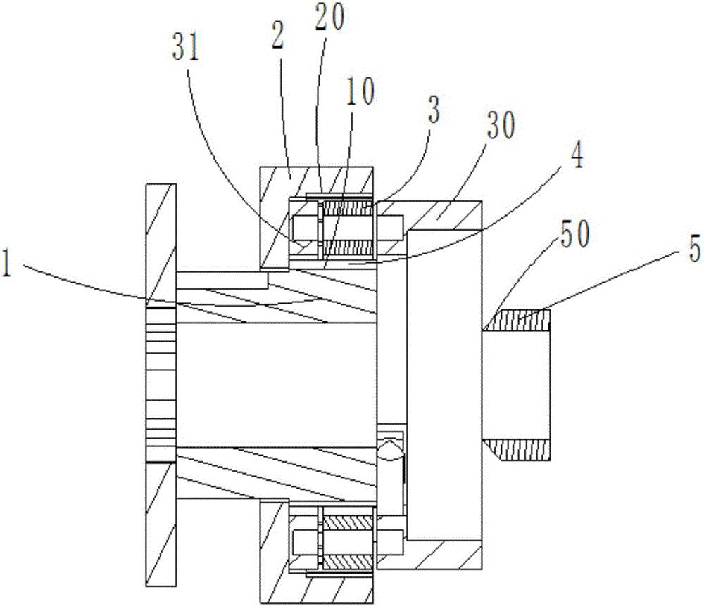
[0023] Please refer to the attached figure 1 As shown, the present invention is a centrifugal shifting device, which is mainly composed of a first transmission member 1, a second transmission member 2 and a shift mechanism 3.

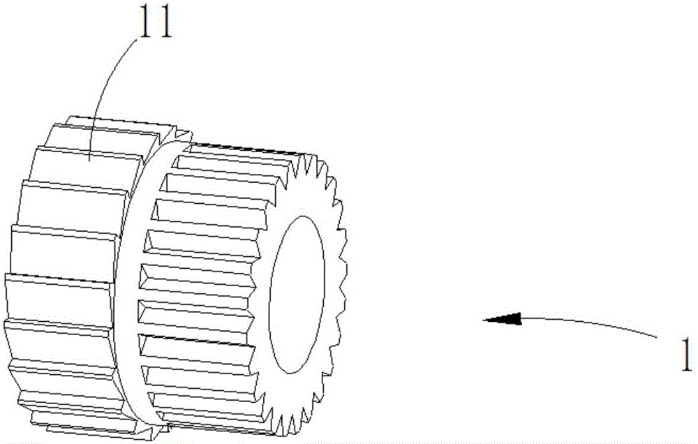
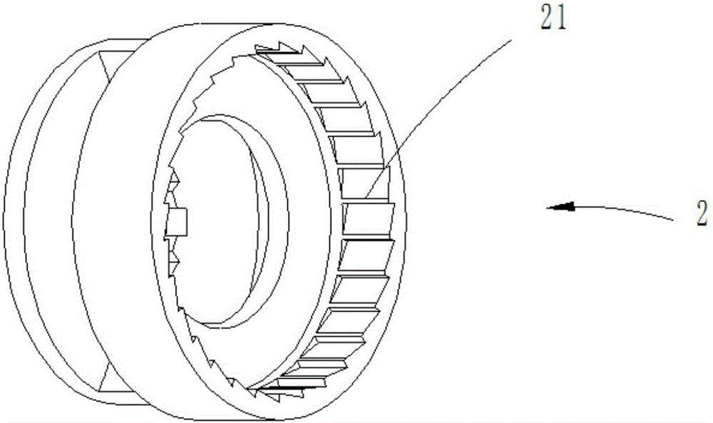
[0024] read on Figure 2 to Figure 5 , the second transmission member 2 is sheathed on the first transmission member 1, a storage chamber 4 is formed between the second transmission member 2 and the first transmission member 1, and the second transmission member 2 is provided with a 4, the first transmission member 1 is provided with an outer wall 10 located in the receiving chamber 4, the outer wall 10 of the first transmission member 1 is provided with a first ratchet 11, and the second transmission member 2 The inner wall 20 is provided with a second ratchet 21 , the first ratchet 11 is integrally formed with the first transmission member 1 , and the second ratchet 21 is integrally formed with the second transmission member 2 . The shifting mechani...

Embodiment 2

[0028] see Figure 6 , the rest of the structure of the centrifugal shifting device in this embodiment is the same as that of Embodiment 1, the difference lies in the structure of the shift member 310, in this embodiment, the counterweight 3101 and the first pawl 3105, the second The pawl 3106 is set at the same end of the mounting part 3100. The working principle of the centrifugal shifting device in this embodiment is: the initial position of the two shifting parts 310 is controlled by the elastic part. axis, the first pawl 3105 of the shifting member 310 meshes with the first ratchet 11, and the first transmission member 1 is meshed with the shifting member 310. As the speed of the first transmission member 1 increases, the shifting The gear frame 30 synchronously rotates faster, and under the action of centrifugal force, the weight 3101 of the gear shifter moves away from the axis, and the second pawl 3106 of the gear shifter 310 engages with the second ratchet 21. At this...


PUM


Abstract

The invention relates to a centrifugal gear shifting device, which comprises a first transmission element, a second transmission element and a gear shifting mechanism, wherein an accommodating cavity is formed between the second transmission element and the first transmission element; the second transmission element is provided with an inner wall positioned in the accommodating cavity; the first transmission element is provided with an outer wall positioned in the accommodating cavity; a first ratchet wheel is arranged in the outer wall position of the first transmission element; a second ratchet wheel is arranged in the inner wall position of the second transmission element; the gear shifting mechanism comprises a gear shifting element frame and a gear shifting element device; the gear shifting element device comprises a plurality of gear shifting elements; the gear shifting elements are connected through balancing elements; each gear shifting element comprises an installing part and a weight balancing block; the installing part comprises an inner surface and an outer surface; the first pallet is arranged on the inner surface of the installing part; the second pallet is arranged on the outer surface of the installing part; an elastic element used for controlling the initial position of the first pallet and the second pallet is arranged on the gear shifting element frame. The centrifugal gear shifting device can realize the automatic gear shifting in the running process.

Description

【Technical field】 [0001] The invention relates to the field of bicycles, in particular to a centrifugal shifting device. 【Background technique】 [0002] Bicycle transmissions are divided into two types: internal transmissions and external transmissions. The external transmission uses an open chain mechanism as the transmission system. By switching the shifter installed in front of the bicycle, the chain is changed to different flywheels to achieve different chain transmission ratios. Since the external derailleur is exposed, it is relatively easy to rust and is easily disturbed by external forces, so regular maintenance is often required. The internal derailleur mainly uses a planetary gear mechanism as the main transmission body, which is sealed inside the hub and passed through multiple layers of special sealing materials. Protection, so rainwater, dust, grease, etc. cannot enter, so there is no need for regular maintenance, and the advantage of maintenance-free is realize...

Claims


Application Information

Patent Timeline
Patent Type & Authority Applications(China)
IPC IPC(8): B62M25/04
CPCB62M25/04
Inventor 黄英可
Owner ZHANGJIAGANG CHUANJUN VEHICLE IND CO LTD
Why Eureka
Try Eureka