Aviation power unit, flight rack of aviation power unit and modularized aircraft of aviation power unit

An aviation power and power unit technology, applied in aircraft, aircraft parts, fuselage frame and other directions, can solve the problems of increasing aircraft weight, poor flight flexibility, inconvenient transportation, etc., achieve flexible assembly forms, improve flight flexibility, The effect of easy and quick assembly

Active Publication Date: 2016-10-12
ZHUHAI PANSHI ELECTRONICS TECH CO LTD
View PDF7 Cites 16 Cited by
  • Summary
  • Abstract
  • Description
  • Claims
  • Application Information

AI Technical Summary

Problems solved by technology

[0004] At present, the aircraft on the market mainly has two structures: 1. The frame is integrally formed, and other parts are connected by bolts; 2. The parts are connected by bolts. Through practice, it is found that the above two structures have the following defects: For the aircraft with integrally formed frame, due to the limitation of volume and shape structure, the processing process is relatively complicated and the scope of application is small; at the same time, when the local transmission is damaged (such as falling, bumping, etc.), it needs to be replaced as a whole , so waste material resources, but also increase the cost, especially the use of multi-rotor multi-axis aircraft, the support arm of this type of aircraft and the main body are generally connected into a whole through anti-skid bolts, resulting in large geometric dimensions of the wing aircraft, not It is easy to transport, and because most of the connections between the support arm and the support plate are anti-skid bolts, the user needs to carry special tools to disassemble and replace each part during maintenance. The entire maintenance process is cumbersome and complicated; As far as the connected aircraft is concerned, the assembly process is cumbersome and the installation efficiency is low; at the same time, the use of a large number of bolts also increases the weight of the aircraft, resulting in poor flight flexibility

Method used


Image

  • Aviation power unit, flight rack of aviation power unit and modularized aircraft of aviation power unit
  • Aviation power unit, flight rack of aviation power unit and modularized aircraft of aviation power unit
  • Aviation power unit, flight rack of aviation power unit and modularized aircraft of aviation power unit

Examples


example 1

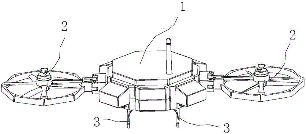
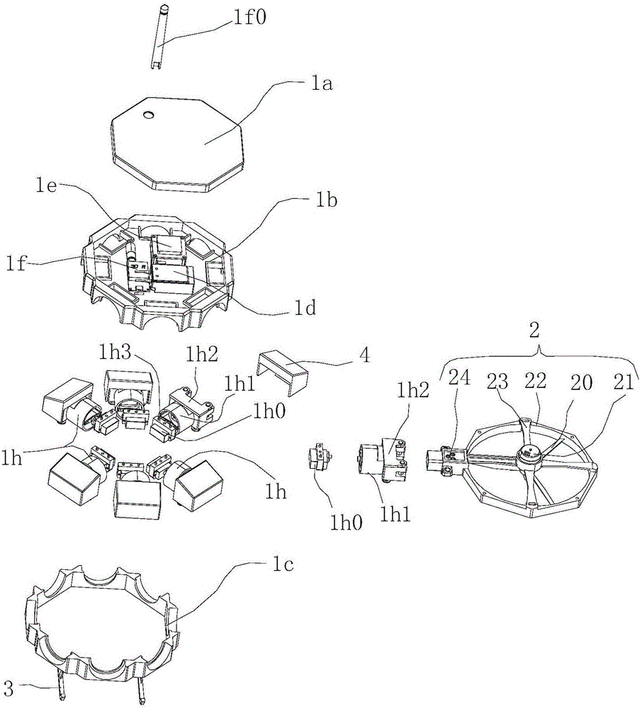
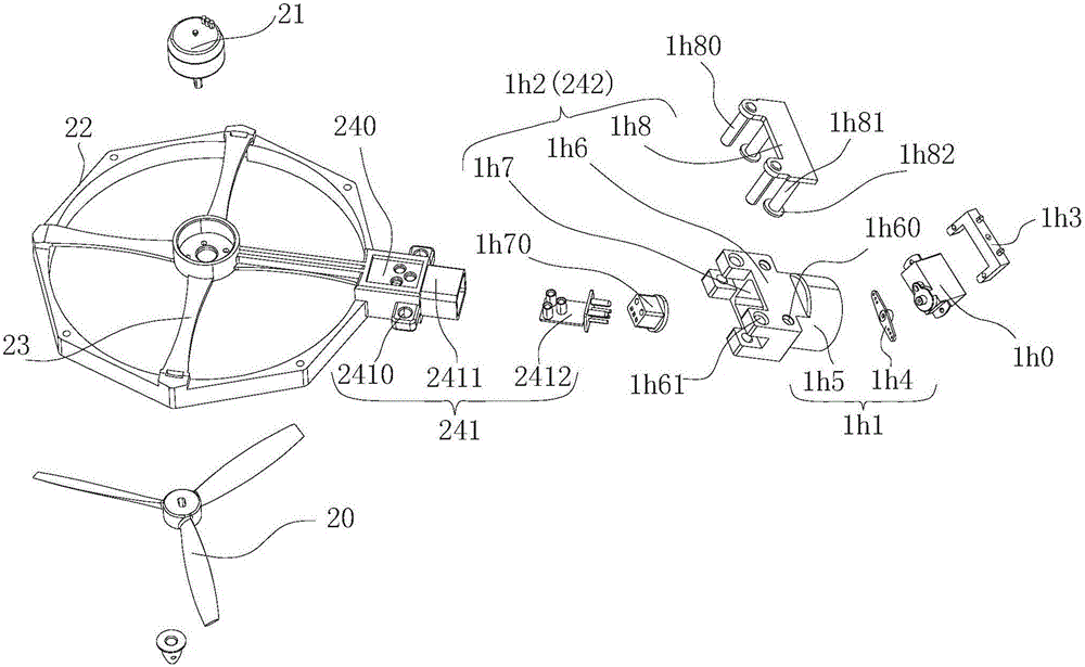
[0049] Modular aircraft such as Figure 1 to Figure 6 As shown, it includes a flight frame 1 and two symmetrical aerodynamic units 2 connected to the periphery of the flight frame; the flight frame 1 includes a top cover 1a and a casing, and the casing consists of an upper casing 1b and a lower casing 1c The upper and lower casings (1b, 1c) are snapped and connected up and down, and the top cover 1a is buckled on the top of the upper casing 1b; a power supply 1d, a main control board 1e and a communication board are installed on the upper side of the upper casing 1b. Module 1f: There are two rotating serial parts 1h as electric rotating installation interfaces symmetrically arranged in the circumferential direction of the upper and lower casings, which can rotate relative to the overall flight frame 1, and each rotating serial part 1h includes a rotor The deflection motor 1h0, the rotation part 1h1 and the pin connection part 1h2, the rotor deflection motor 1h0 is fixed on the...

Embodiment 2

[0055] Such as Figure 7 As shown, the only difference between this embodiment and Embodiment 1 is that three evenly distributed aerodynamic power units 2 are connected to the outer periphery of the flight frame 1, so that greater power can be provided, and the stability control of flying is more stable. reliable.

Embodiment 3

[0057] Such as Figure 8 As shown, the only difference between this embodiment and Embodiment 1 is that four evenly distributed aerodynamic units 2 are connected to the outer periphery of the flight frame 1, so that the deflection of two symmetrically arranged aerodynamic units 2 is controlled. It can control the flight direction of the entire aircraft, and the other two aerodynamic power units 2 can also effectively provide lift when the aircraft changes direction, ensuring that the modular aircraft can continue to lift while effectively changing the direction, and the stability control of the flight more reliable. When one of the aerodynamic power units fails, another aerodynamic power unit opposite to it at 180 degrees can be shut down, relying on the rest of the aerodynamic power units to continue flying, greatly improving safety and reliability.


PUM


Abstract

The invention relates to an aviation power unit, a flight rack of the aviation power unit and a modularized aircraft of the aviation power unit. Multiple interfaces connected with the aviation power unit are arranged on the periphery of the flight rack. The one or more serial-connected aviation power units or the aviation power units overlaid layer by layer can be arranged on the periphery of the flight rack in different manners, and modularized combination manners are achieved so as to provide various forms of power drive manners. Therefore, the modularized aircraft formed by combining the aviation power units and the flight rack is simple in structure, convenient to assemble, high in efficiency, flexible and variable in assembling manner and capable of meeting different assembling requirements of users.

Description

【Technical field】 [0001] The invention relates to aviation flight equipment, in particular to an aviation power unit, its flight frame and a modular aircraft. 【Background technique】 [0002] At present, multi-axis aircraft has the characteristics of low cost, easy operation, low risk and ultra-low altitude flight. It can use the camera equipment on board to take pictures, obtain image data, and send the obtained image data back to the ground. Multi-axis aircraft has been widely used in aerial photography, power line inspection, aerial reconnaissance, simulated flight, subsidized unmanned aerial vehicles and other fields, for monitoring evidence collection and observation of special locations, etc., and can realize the transmission of on-site video images for command It is an important tool for obtaining information for the reader to make decisions and judge. In addition, multicopters with simple structures are also widely loved in the field of toys. [0003] At present, ai...

Claims


Application Information

Patent Timeline
Patent Type & Authority Applications(China)
IPC IPC(8): B64C1/16B64C1/06B64C27/08B64C27/12
CPCB64C1/061B64C1/16B64C27/08B64C27/12
Inventor 何春旺
Owner ZHUHAI PANSHI ELECTRONICS TECH CO LTD
Why Eureka
Try Eureka