Pneumatic layout of dual flying wings of UAV (Unmanned Aerial Vehicle)

A technology of aerodynamic layout and unmanned aerial vehicle, applied in the direction of unmanned aerial vehicle, motor vehicle, wing shape, etc., can solve the problems of poor handling performance and poor stability, and achieve good longitudinal stability and lateral stability. Good, good heading stability effect

Inactive Publication Date: 2016-10-12
NAVAL AERONAUTICAL & ASTRONAUTICAL UNIV PLA
View PDF9 Cites 12 Cited by
  • Summary
  • Abstract
  • Description
  • Claims
  • Application Information

AI Technical Summary

Problems solved by technology

However, the shortcomings of the flying wing layout are also obvious, mainly in poor control performance and poor stability, and it needs to completely rely on electronic sensors to control the rudder surfaces of the wings and control the vector thrust of the engine

Method used


Image

  • Pneumatic layout of dual flying wings of UAV (Unmanned Aerial Vehicle)
  • Pneumatic layout of dual flying wings of UAV (Unmanned Aerial Vehicle)
  • Pneumatic layout of dual flying wings of UAV (Unmanned Aerial Vehicle)

Examples


Embodiment Construction

[0025] The following will be combined with Figure 1-10 The present invention is described in further detail with embodiment.

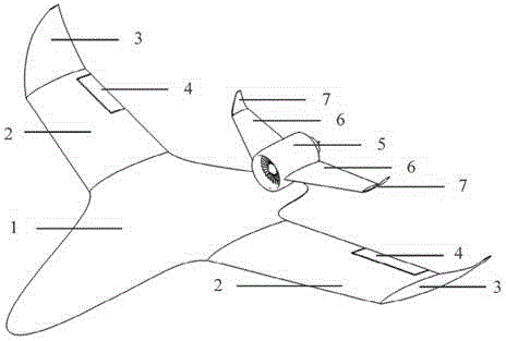
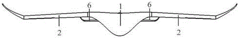
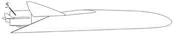
[0026] An embodiment of the aerodynamic layout of the double-flying wing of an unmanned aerial vehicle is characterized in that it includes: the aerodynamic layout of the wing-body fusion body flying wing, the layout where the turbofan engine is installed above the rear section of the wing-body fusion body flying wing, and the installation of a full-motion horizontal tail The aerodynamic layout on both sides of the turbofan engine outer wall nacelle (5), wherein the fuselage (1), wings (2), winglets (3) and direction ailerons (4) together form the high lift The wing-body fusion body flying wing of drag ratio, the flat tail (6) and the flat tail winglet (7) together form the described full-motion horizontal tail that provides positive lift when leveling off, and the wing-body fusion body flying wing and the full-motion flat tail together form the The ...


PUM


Abstract

The invention relates to a pneumatic layout of dual flying wings of a UAV (Unmanned Aerial Vehicle). The pneumatic layout is characterized by comprising a pneumatic layout of a blended wing body flying wing, a layout of installing a turbofan engine above the rear section of the blended wing body flying wing and a pneumatic layout of installing a stabilator at two sides of a nacelle on the outer wall of the turbofan engine, wherein the blended wing body flying wing with a high lift-to-drag ratio is formed by a fuselage, wings, wingtip winglets and direction ailerons together; the stabilator which is used for providing a positive lifting force during flight trimming of the UAV is formed by horizontal tails and horizontal tail winglets, and the dual flying wings are formed by the blended wing body flying wing and the stabilator together. According to the pneumatic layout of the dual flying wings of the UAV, disclosed by the invention, the UAV has high lift-to-drag ratio, good operability and high stability, and the pneumatic layout has the advantage of good stealth performance.

Description

technical field [0001] The invention relates to an aerodynamic layout of double flying wings of an unmanned aerial vehicle, belonging to the field of aviation technology. Background technique [0002] At present, the flying wing layout is a layout form widely used in advanced aircraft, and it is one of the hot issues in the research of aircraft aerodynamic layout in recent years. Flying wings are famous for their high lift-to-drag ratio and good stealth performance among the large aircraft families in the world today. The representative of Flying Wing is the X-47B experimental carrier-based UAV of the United States. This type of UAV successfully made its first flight on February 4, 2011, and successfully completed a series of ground and ship surface tests in 2013. However, the shortcomings of the flying wing layout are also obvious, mainly in poor control performance and poor stability, and it needs to completely rely on electronic sensors to control the rudder surfaces of ...

Claims


Application Information

Patent Timeline
Patent Type & Authority Applications(China)
IPC IPC(8): B64C3/10B64C3/16
CPCB64C3/10B64C3/16B64U30/10
Inventor 岳奎志韩维柳文林
Owner NAVAL AERONAUTICAL & ASTRONAUTICAL UNIV PLA
Why Eureka
Try Eureka