Unmanned aerial vehicle nacelle retracting mechanism and assembly method
A retractable mechanism and pod technology, applied in aircraft parts, transportation and packaging, etc., can solve the problems of poor use effect, large size, and complex UAV pod retractable mechanism, achieving good versatility and structure. Simple and compact, easy to install and maintain
- Summary
- Abstract
- Description
- Claims
- Application Information
AI Technical Summary
Problems solved by technology
Method used
Image
Examples
specific Embodiment approach 1
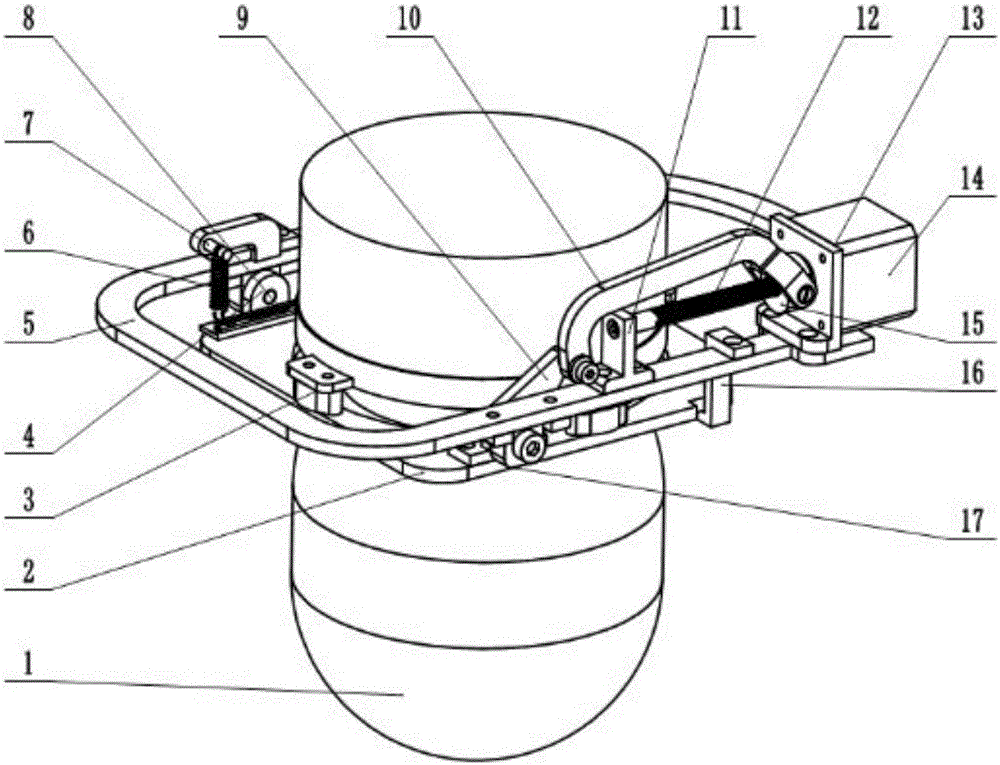
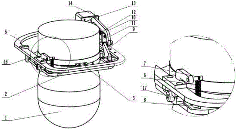
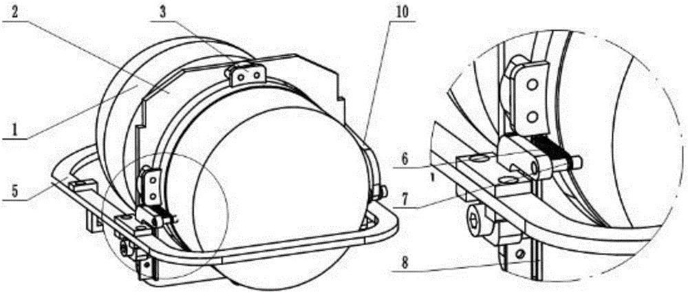
[0023] Specific implementation mode 1. Combination Figure 1 to Figure 5 Description of this embodiment, a UAV pod retractable mechanism is mainly composed of four parts: a fixed assembly, a rotating assembly, a slider crank mechanism, and an auxiliary locking mechanism. The fixed plate lug 17 of the hinged fixed assembly and the moving plate lug 4 of the rotating assembly make the fixed assembly and the rotating assembly connected as a rotating pair; the slider crank mechanism drives the rotating assembly to rotate through the crank 9; the auxiliary locking mechanism changes the rotating assembly During the rotation process, the hanging point position of the locking tension spring 6 realizes the reversing of the locking torque, and locks the rotating assembly to the fixed assembly in the state of lowering and retracting.
[0024] The fixed assembly is composed of a frame 5 and a fixed plate lug 17 . The frame 5 is used to install and fix the whole mechanism on the drone body...
specific Embodiment approach 2
[0027] Embodiment 2. This embodiment is an assembly process of a UAV pod retractable mechanism described in Embodiment 1: it is realized by the following steps:
[0028] Step 1: Fix the lifting lug 4 of the moving plate, the crank 9 and the sliding rail 8 of the moving hanging point on the vibration isolation plate 2 .
[0029] Step 2: Fix the pod 1 on the vibration isolation plate through the shock absorber 3 .
[0030] Step 3: Fix the fixed hanging point 7, the screw support 11, the motor base 13, the lower limit block 16, and the fixed plate lug 17 on the frame 5.
[0031] Step 4: Install the motor 14 on the motor base 13 .
[0032] Step five, put the slider 15 on the screw rod 12, connect one end of the screw rod 12 with the motor 14, and support the other end with the screw rod support 11.
[0033] Step 6: Hinge the lifting lug 17 of the fixed plate with the lifting lug 4 of the moving plate.
[0034] Step seven, connect the slider 15 and the crank 9 with the connectin...
PUM
 Abstract
Description
Claims
Application Information
 - R&D
- Intellectual Property
- Life Sciences
- Materials
- Tech Scout
- Unparalleled Data Quality
- Higher Quality Content
- 60% Fewer Hallucinations
Browse by: Latest US Patents, China's latest patents, Technical Efficacy Thesaurus, Application Domain, Technology Topic, Popular Technical Reports.
© 2025 PatSnap. All rights reserved.Legal|Privacy policy|Modern Slavery Act Transparency Statement|Sitemap|About US| Contact US: help@patsnap.com


