A "two-point" line-element method for planar alignment design of road routes

A line element method and line element technology, which is applied in the field of planar alignment design of road routes, can solve problems such as lack of flexibility, shape of line element, end point position and tangent direction of end point, etc.

Inactive Publication Date: 2017-12-05
DALIAN UNIV OF TECH
View PDF5 Cites 0 Cited by
  • Summary
  • Abstract
  • Description
  • Claims
  • Application Information

AI Technical Summary

Problems solved by technology

The dynamic interactive line element building block method is simple and intuitive, and can greatly improve the design effect and design efficiency. Its disadvantages are: ① Since the curve length or end point half is used as the control parameter, the end point E of the new line element designed is usually equal to The reference coordinate point E′ during the dragging process of the mouse does not coincide, which makes it difficult to effectively control the shape, end position and end tangent direction of the newly designed line element
②Generally, only one line element type (one of straight line, circular curve and clothoid line) is pre-set, and only one established line element curve that satisfies the constraints is displayed in real time during the dynamic design process, and the designer has no choice and lacks flexibility flexibility

Method used


Image

  • A "two-point" line-element method for planar alignment design of road routes
  • A "two-point" line-element method for planar alignment design of road routes
  • A "two-point" line-element method for planar alignment design of road routes

Examples


Embodiment Construction

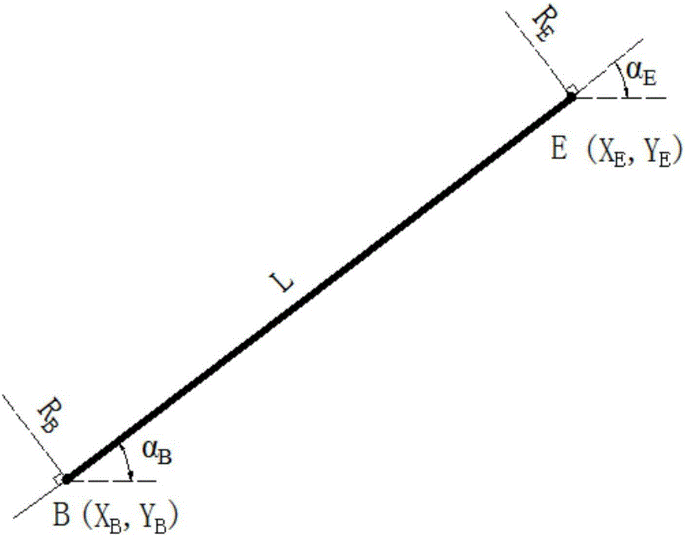
[0163] Step 1: Determine the relevant parameters of the starting point B of the line element

[0164] It is necessary to determine the starting point B coordinate of the line element (x B ,y B ), starting point tangent angle α B and starting radius R B There are 3 independent parameters in total.

[0165] If it is the first line element, the coordinates of the starting point B adopt the coordinates of the starting point A of the road section, that is, x B =x A 、y B =y A ; Need to set the starting point tangential angle α separately B and starting radius R B .

[0166] For the rest of the line elements, according to the principle of linear continuity, it is only necessary to change the position of the end point E and the tangential angle of the end point α of the previous completed line element E and end radius R E As the starting point parameter of the current design line element, namely: x B =x E 、y B =y E , α B = α E , R B = R E .

[0167] where tangent l...


PUM


Abstract

The invention relates to a ''two points'' line element method for road route plane alignment design, and belongs to the technical field of road route plane alignment design curve methods. The ''two points'' line element method is characterized by comprising six basic line element types of a straight tangent, a circular curve, a forward / backward complete type convolute curve, and a forward / backward incomplete type convolute curve, and comprising eight basic parameters of a coordinate, a tangential clearance angle and a radius which are relevant with a starting point of the line element, a coordinate, a tangential clearance angle and a radius which are relevant with an end point of the line element, a line element deflection angle and a line element length. Four typical independent parameters are a coordinate of the starting point, a tangential clearance angle of the starting point, a radius of the starting point and a coordinate of the end point. During the process of line element designing, three parameters relevant with the starting point are known, so that a person only needs to set the coordinate of the end point, then the only six basic line element type element curve can be determined, just like that a straight line is only determined by two points. The ''two points'' line element method disclosed by the invention has the effects and benefits that the only six basic line element type element curve can be determined through the two points; the line element end point position, the line element shape and the route alignment are easy to control, the control of coordinate positions to the line element is emphasized, and conforming to the custom of route design and coordinate control of construction paying-off is realized.

Description

technical field [0001] The invention belongs to the technical field of planar alignment design of road routes, and relates to a curve method for planar alignment design, in particular to a "two-point" line element method for planar alignment design of road routes. technical background [0002] At present, the planar alignment design methods in my country mainly include the wire method and the curve method. The wire method is a traditional design method, which is characterized by determining the flat curves such as circular curves and transitional curves based on the design of straight wires connected end to end. The direction of the route plays the main control role, and the role of the circular curve and the transitional curve is to ensure the smoothness of the line shape. [0003] The traditional conductor design method is difficult to meet the complex plane alignment design requirements, especially the plane alignment design in mountainous areas and the interchange ramp al...

Claims


Application Information

Patent Timeline
Patent Type & Authority Patents(China)
IPC IPC(8): E01C1/00
CPCE01C1/002
Inventor 李玉华周长红赵延庆欧阳剑刘也嘉刘佳音孙伊人刘婉秋陈静云李亚龙
Owner DALIAN UNIV OF TECH
Why Eureka
Try Eureka