High-efficiency energy-saving fan

A high-efficiency energy-saving fan technology, applied in mechanical equipment, engine functions, machines/engines, etc., can solve the problems of low overall fan efficiency, reduced production efficiency, high gas loss, etc., to improve fan efficiency, improve efficiency, and reduce energy consumption Effect

Inactive Publication Date: 2016-10-12
重庆沃亚机械有限公司
View PDF13 Cites 7 Cited by
  • Summary
  • Abstract
  • Description
  • Claims
  • Application Information

AI Technical Summary

Problems solved by technology

[0003] The disadvantages of the existing fans are: due to factors such as turbulence and turbulence between gases, the loss of gas in the entire fan system is high, the overall efficiency of the fan is low, and the production efficiency is reduced. conditions, requiring high energy consumption

Method used


Image

  • High-efficiency energy-saving fan
  • High-efficiency energy-saving fan
  • High-efficiency energy-saving fan

Examples


Embodiment Construction

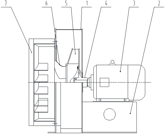
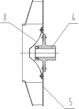
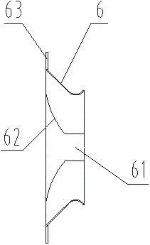
[0024] like figure 1 As shown, the high-efficiency energy-saving fan of the present invention includes a casing 1, a base 2 and a motor 3 installed on the base 2, the output end of the motor 3 is connected with a shaft sleeve 4, and the shaft sleeve 4 can rotate synchronously with the output shaft of the motor; The casing 1 is provided with an air inlet chamber 6 and the impeller 5 in sequence, and the outer edge of the shaft sleeve 4 is fixedly connected to the back plate of the impeller 5 by bolts to drive the impeller to rotate; the air inlet side of the casing 1 is provided with an air inlet box 7. The air inlet of the air inlet chamber 6 communicates with the air outlet of the air inlet box 7, and the air outlet of the air inlet chamber 6 communicates with the air inlet of the impeller 5. When working, the gas first passes through the air inlet box 7, and then passes through the air inlet chamber 6 enters the impeller 5, after being pressurized in the impeller 5, it is di...


PUM


Abstract

The invention provides a high-efficiency energy-saving fan. The high-efficiency energy-saving fan comprises a machine casing, wherein a gas inlet tank is arranged on a gas inlet side of the machine casing; a gas inlet chamber and a vane wheel are sequentially arranged in the machine casing; a wind inlet of the gas inlet chamber communicates with a wind outlet of the gas inlet tank; the wind outlet of the gas inlet chamber communicates with the wind inlet of the vane wheel; a conical dish is arranged in the vane wheel; a plurality of spiral guide vanes of which the rotating direction is consistent with that of the vane wheel are arranged on the inner wall of the gas inlet chamber; a plurality of guide vanes which are mutually arranged in parallel are arranged in the gas inlet tank; the tail ends of the guide vanes are deflected towards the direction of the wind outlet of the gas inlet tank. According to the high-efficiency energy-saving fan disclosed by the invention, components of a whole fan system are modified, and the mobility of a wind current in the whole fan system is changed, so that losses of the wind current in the whole fan system are reduced, the efficiency of the whole fan is improved, and the industrial production efficiency is further improved; under same working conditions, the energy consumption of the fan disclosed by the invention is reduced, and a producing task is completed at low energy consumption.

Description

technical field [0001] The invention belongs to the technical field of fans, and in particular relates to a high-efficiency and energy-saving fan. Background technique [0002] Fan is a machine that relies on input mechanical energy to increase gas pressure and discharge gas. At present, fans have been widely used in industrial production, mainly for ventilation, dust removal and cooling. Nowadays, with the change of our country's national conditions, energy saving has become the key to industrial production. However, the existing fan is mainly composed of a casing, an air inlet chamber and an impeller installed in the casing in sequence. Of course, some types of fans also have An air intake box is installed, the air inlet of the air inlet chamber communicates with the air outlet of the air inlet box, and the air outlet of the air inlet chamber communicates with the air inlet of the impeller. When working, the air first passes through the air inlet box, and then enters from ...

Claims


Application Information

Patent Timeline
Patent Type & Authority Applications(China)
IPC IPC(8): F04D29/28F04D29/42F04D29/44F04D29/66
CPCF04D29/281F04D29/4226F04D29/444F04D29/666F04D29/667F05D2260/14
Inventor 高峰李世庆向光权
Owner 重庆沃亚机械有限公司
Why Eureka
Try Eureka