System for cleaning streetlamp through raindrops

A technology for cleaning and street lamps, applied in the direction of cleaning methods using tools, cleaning methods and utensils, and components of lighting devices, etc., can solve the problem of increasing the weight of street lamp poles and lamp bodies, rainwater washing parts and limited strength, and affecting street lamps Problems such as structure and strength, to achieve the effect of ensuring long-term normal use, improving cleanliness, and stable structure

Inactive Publication Date: 2016-10-12
HUNAN CITY UNIV
View PDF4 Cites 10 Cited by
  • Summary
  • Abstract
  • Description
  • Claims
  • Application Information

AI Technical Summary

Problems solved by technology

[0002] Traditional street lamps cannot automatically clean the lamp body, and because the lamp pole is long, manual scrubbing is difficult, so it can only be washed by natural rainwater, and the lighting part of the lamp body is located below, so the rainwater washing position and strength are very limited. Over time, the lamp body of the street lamp is covered by dust and stains, resulting in a decrease in lighting intensity and lighting effect. The existing automatic cleaning street lamps are generally equipped with a rainwater collection box, and the street lamp is cleaned after collecting full rainwater. The rainwater collection box is filled with rainwater Increased the weight of the street lamp pole and lamp body, affecting the structure and strength of the street lamp

Method used


Image

  • System for cleaning streetlamp through raindrops
  • System for cleaning streetlamp through raindrops
  • System for cleaning streetlamp through raindrops

Examples


Embodiment Construction

[0027] In order to enable those skilled in the art to better understand the technical solution of the present invention, the present invention will be described in detail below in conjunction with the accompanying drawings. The description in this part is only exemplary and explanatory, and should not have any limiting effect on the protection scope of the present invention. .

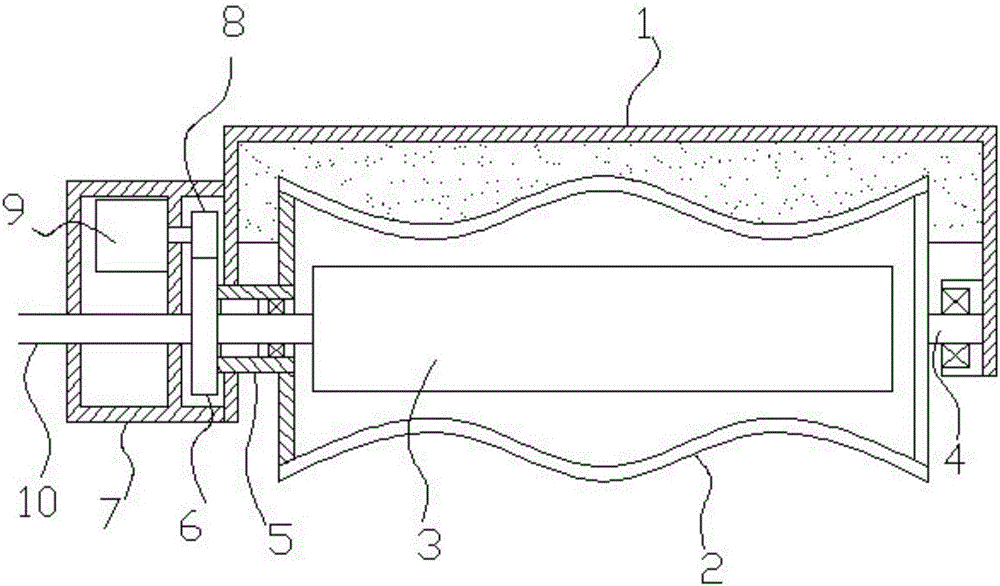
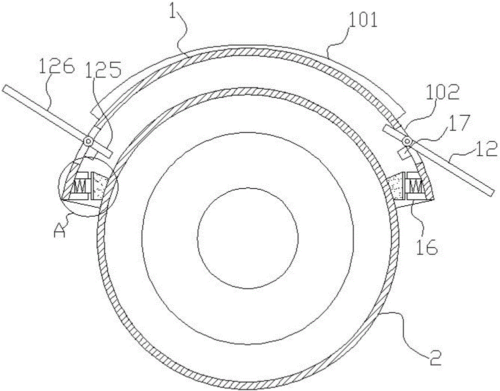
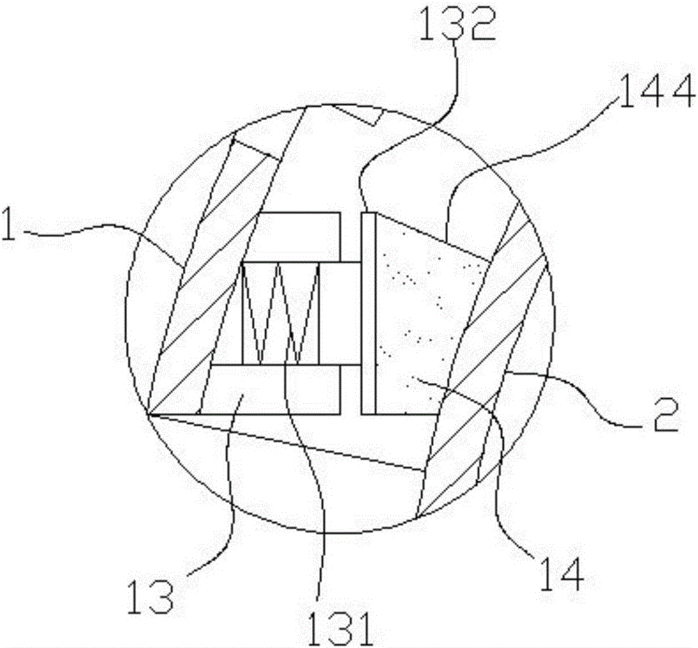
[0028] Such as Figure 1-Figure 7 As shown, the specific structure of the present invention is: a system for cleaning street lamps using raindrops, which includes a lamp housing plate 1 fixed on the mounting frame 7, a rotating lampshade 2 is arranged below the lamp housing board 1; A lamp body 3 is provided; one end of the rotating lampshade 2 is provided with a sleeve shaft 5 connected to a motor 9, and the motor 9 is arranged in the mounting frame 7; wipers 16 are provided on both sides of the inner wall of the lamp housing plate 1; the lamp Both sides of the shell plate 1 are located above the wip...


PUM


Abstract

This invention discloses a system for cleaning a streetlamp through raindrops. The system comprises a lamp shell plate fixed to an installing frame; a rotating lampshade is arranged below the lamp shell plate; a lamp body is arranged in the rotating lampshade; a sleeve shaft is arranged at one end of the rotating lampshade and connected with a motor; the motor is arranged in the installing frame; wipers are arranged on the two sides of the inner wall of the lamp shell plate; rain guiding holes are formed in the portions, above the wipers, of the two sides of the lamp shell plate; rain guiding plates are hinged in the rain guiding holes through torsion springs; each rain guiding plate comprises a lower short plate and an upper long plate; limiting lugs are arranged at the two ends of each lower short plate and provided with iron blocks; electromagnets are arranged on the lamp shell plate and located below the rain guiding holes; each lower short plate is located on the inner side of the lamp shell plate, and each upper long plate is located on the outer side of the lamp shell plate; each wiper comprises an elastic base fixed to the lamp shell plate, a telescopic base is arranged on each elastic base, and a compression spring is arranged at the bottom of each elastic base; the telescopic bases are connected with fixing strips; and sponge brushes are arranged on the fixing strips. The system can improve the protecting strength of the streetlamp body, the streetlamp can be cleaned in real time through rainwater, the cleaning effect is good, and energy consumption is low.

Description

technical field [0001] The invention relates to the technical field of street lamp design, in particular to a system for cleaning street lamps by using raindrops. Background technique [0002] Traditional street lamps cannot automatically clean the lamp body, and because the lamp pole is long, manual scrubbing is difficult, so it can only be washed by natural rainwater, and the lighting part of the lamp body is located below, so the rainwater washing position and strength are very limited. Over time, the lamp body of the street lamp is covered by dust and stains, resulting in a decrease in lighting intensity and lighting effect. The existing automatic cleaning street lamps are generally equipped with a rainwater collection box, and the street lamp is cleaned after collecting full rainwater. The rainwater collection box is filled with rainwater The weight of the street lamp pole and lamp body is increased, which affects the structure and strength of the street lamp. Content...

Claims


Application Information

Patent Timeline
Patent Type & Authority Applications(China)
IPC IPC(8): F21S8/08F21V33/00F21V29/70B08B1/02B08B1/00
CPCB08B1/002B08B1/006B08B1/02F21S8/085F21V29/70F21V33/00
Inventor 李加升
Owner HUNAN CITY UNIV
Why Eureka
Try Eureka