Optical scanning device, image forming device, aperture fixing method

A technology of optical scanning device and main scanning direction, which is applied in the field of optical scanning device and image forming device, can solve the problems that hinder the miniaturization of the sub-scanning direction of the optical scanning device, and achieve the effect of miniaturization

Active Publication Date: 2019-03-12
KYOCERA DOCUMENT SOLUTIONS INC
View PDF6 Cites 0 Cited by
  • Summary
  • Abstract
  • Description
  • Claims
  • Application Information

AI Technical Summary

Problems solved by technology

[0003] However, in the above configuration, when viewed from the polygon mirror, a plurality of light sources are arranged bidirectionally across the sub-scanning direction, and the arrangement of the substrates on which the respective light sources are mounted may hinder the miniaturization of the optical scanning device in the sub-scanning direction.

Method used


Image

  • Optical scanning device, image forming device, aperture fixing method
  • Optical scanning device, image forming device, aperture fixing method
  • Optical scanning device, image forming device, aperture fixing method

Examples


no. 1 approach

[0028] Embodiments of the present invention are described below with reference to the drawings for understanding of the present invention. In addition, the following embodiment is an example which actualized this invention, and is not intended to limit the technical scope of this invention.

[0029] (Schematic Configuration of Image Forming Apparatus 10 )

[0030] First, the schematic configuration of the image forming apparatus 10 according to the embodiment of the present invention will be described.

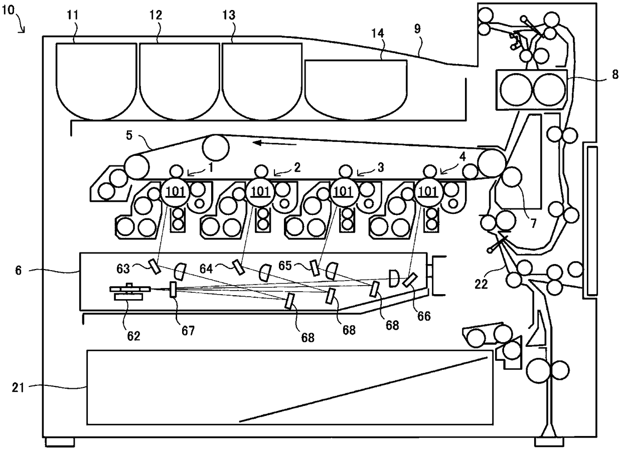
[0031] Such as figure 1 As shown, the image forming apparatus 10 is equipped with a plurality of image forming units 1 to 4, an intermediate transfer belt 5, an optical scanning device 6, a second transfer roller 7, a fixing device 8, a paper output tray 9, a paper feeding cassette 21 and the color printer of conveying channel 22 etc. Furthermore, the image forming apparatus 10 forms a black-and-white image or a color image on a sheet based on the input image data. The she...

no. 2 approach

[0079] When adjusting the fixed state of the aperture 82, the adjustment can be performed while capturing the laser light with a camera having an imaging element such as a CCD. For example, the camera is disposed between the cylindrical lens 77 and the polygon mirror 62 during adjustment work, and is removed after the adjustment work is completed.

[0080] However, for example, when the focal length of the scanning lens such as the Fθ lens provided in the optical scanning device 6 is long, the width of the laser light passing through the aperture 82 in the main scanning direction D1 becomes large. Therefore, if the size of the camera is small relative to the laser width of the main scanning direction D1, then as Figure 14A As shown, in the captured image P10 of the camera, it is possible that the end of the laser beam in the main scanning direction D1 is not captured. Additionally, if Figure 14A ~ Figure 14C As shown, the camera is arranged in the optical scanning device 6...

no. 3 approach

[0091] Next, the image forming apparatus 10 according to the third embodiment will be described. In addition, the same code|symbol is attached|subjected to the structure similar to the said 2nd Embodiment, and the description is abbreviate|omitted.

[0092] Such as Figure 16A As shown, the aperture 82 has a notch 914 in addition to the notch 97, and the notch 914 is formed in a direction parallel to the longitudinal direction D4 of the opening 83, into which a shield described later can be inserted. Build 915. Here, the notch 914 is an example of a second notch, and the shielding member 915 is an example of a second shielding member.

[0093] The notch 914 is formed at a predetermined position perpendicular to the center of the insertion direction D5 in the longitudinal direction D4 of the opening 83 and coincides with the center of the opening 83 in the insertion direction D5. The notch 914 is a recess formed on the surface (ie, the front surface) on the downstream side i...


PUM


Abstract

The present invention provides a light scanning device including a scanning member, a plurality of light sources, a first reflecting mirror and a second reflecting mirror, an image forming device, and a diaphragm fixing method. The scanning member scans the incident laser light in a predetermined main scanning direction. The plurality of light sources irradiate the laser light from different positions in the sub-scanning direction perpendicular to the optical axis direction of the laser light and the main scanning direction, respectively. The first reflecting mirror is tilted with the main scanning direction as a rotation axis, and is tilted with the sub-scanning direction as a rotation axis, and reflects laser light irradiated from each of the light sources, respectively. The second mirror is tilted with the main scanning direction as the rotation axis, and the second mirror is tilted with the sub-scanning direction as the rotation axis, and each of the laser beams reflected by the first reflection mirror is directed toward the scanning Component reflection.

Description

technical field [0001] The present invention relates to an optical scanning device for scanning laser light, an image forming apparatus including the optical scanning device, and a diaphragm fixing method. Background technique [0002] An electrophotographic image forming apparatus includes an optical scanning device that scans laser light onto the surface of the photoreceptor to form an electrostatic latent image on the photoreceptor. The light scanning device includes a light source for irradiating laser light, a polygon mirror for scanning the laser light irradiated from the light source, and the like. Also, a constitution in which laser light irradiated from a plurality of light sources is scanned by a polygonal mirror is known. Specifically, the plurality of light sources are arranged at different positions in the direction perpendicular to the optical axis of the laser light and in the sub-scanning direction which is the main scanning direction of the laser light. In...

Claims


Application Information

Patent Timeline
Patent Type & Authority Patents(China)
IPC IPC(8): G02B26/12G03G15/04
CPCG02B26/123G03G15/04036B41J2/473G02B26/124H04N1/0283H04N1/02885H04N1/06G03G15/043H04N2201/0094H04N2201/02493
Inventor 吉田真悟水谷秀次栗原隆之内田幸佑
Owner KYOCERA DOCUMENT SOLUTIONS INC
Why Eureka
Try Eureka