Infrared detector and its forming method, infrared detector packaging structure and its method

An infrared detector and packaging structure technology, applied in the field of sensing, can solve problems such as low efficiency and high cost, and achieve the effects of improving production efficiency, reducing process costs, and reducing packaging costs

Active Publication Date: 2021-12-10
ZHEJIANG DALI TECH
View PDF5 Cites 0 Cited by
  • Summary
  • Abstract
  • Description
  • Claims
  • Application Information

AI Technical Summary

Problems solved by technology

Since hundreds of detector chips can be cut out from a single wafer, this form of packaging is inefficient and expensive
Currently, packaging costs for uncooled infrared detectors using traditional packaging types account for 90% of the overall detector cost

Method used


Image

  • Infrared detector and its forming method, infrared detector packaging structure and its method
  • Infrared detector and its forming method, infrared detector packaging structure and its method
  • Infrared detector and its forming method, infrared detector packaging structure and its method

Examples


Embodiment Construction

[0036] The specific implementations of the infrared detector and its forming method, the infrared detector packaging structure and its method provided by the present invention will be described in detail below in conjunction with the accompanying drawings.

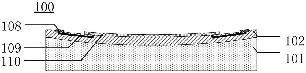
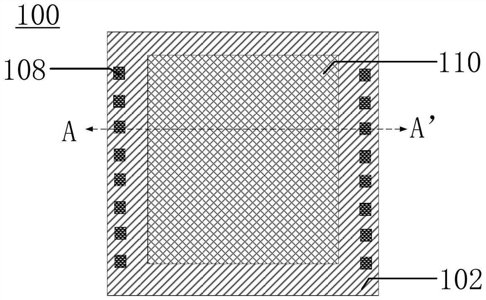
[0037] Please refer to Figure 1A to Figure 1B It is a structural schematic diagram of an infrared detector according to a specific embodiment of the present invention, wherein, Figure 1B For a top view diagram, Figure 1A for along Figure 1B Schematic cross-sectional view of the secant line AA'.

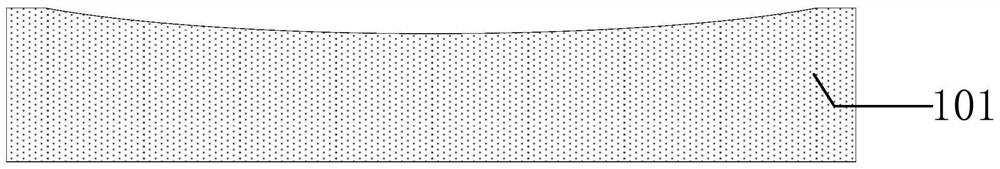
[0038] The infrared detector 100 includes: a substrate 101, the surface of the substrate 101 has a depression, and the bottom surface of the depression is a curved surface; the detector includes a substrate 102, and the substrate has an opposite first surface and a second surface , a sensor circuit 110 is formed on the first surface; the detector is fixed on the surface of the substrate 101, and the second surface of the sub...


PUM


Abstract

The present invention relates to an infrared detector and its forming method, an infrared detector packaging structure and its forming method. The infrared detector includes: a detector including a substrate, and the substrate has a first surface and a second surface opposite to each other. A sensing circuit is formed on the first surface; a base, the base surface has a depression, the bottom surface of the depression is a curved surface, and the position of the depression corresponds to the sensing circuit; the detector is fixed on the base surface, the second surface of the substrate is in contact with the bottom surface of the depression, so that the sensing surface of the detector is a curved surface. The infrared detector has a relatively low cost.

Description

technical field [0001] The invention relates to the field of sensing technology, in particular to an infrared detector and a forming method thereof, an infrared detector packaging structure and a packaging method thereof. Background technique [0002] Infrared imaging technology is widely used in military, industrial, agricultural, medical, forest fire prevention, environmental protection and other fields, and its core component is the infrared focal plane array (IRFPA). According to the working principle, it can be divided into: cooled infrared detector and uncooled infrared detector. [0003] Refrigerated detectors mainly use the narrow-bandgap semiconductor photoelectric effect to convert infrared light signals into electrical signals, also known as photon detectors, and usually work at 77K or lower temperatures, which requires bulky and expensive refrigeration equipment. In addition, materials such as HgCdTe and InSb used to make photon detectors are expensive, difficul...

Claims


Application Information

Patent Timeline
Patent Type & Authority Patents(China)
IPC IPC(8): H01L31/0203H01L31/09H01L31/18G01J5/10
CPCH01L31/0203H01L31/09H01L31/18G01J5/10Y02P70/50
Inventor 钱良山张云胜姜利军
Owner ZHEJIANG DALI TECH
Why Eureka
Try Eureka