Laser crystal, laser and preparation method of hundred-picosecond laser

A laser crystal and laser technology, applied in the field of optics, can solve problems such as unfavorable operation, large size, and poor treatment effect, achieve compact structure design, improve threshold, and achieve the effect of miniaturization

Pending Publication Date: 2022-01-04
TECHNICAL INST OF PHYSICS & CHEMISTRY - CHINESE ACAD OF SCI
View PDF2 Cites 0 Cited by
  • Summary
  • Abstract
  • Description
  • Claims
  • Application Information

AI Technical Summary

Problems solved by technology

Among them, the passive Q-switching technology is widely favored because of its strong stability and good laser beam quality. The passive Q-switching technology is to insert a saturable absorber in the optical path and reasonably design the cavity shape to obtain a hundred picosecond laser pulse output. However, At present, the pulse width obtained by common passive Q-switched lasers is generally above 500ps, and the output single pulse energy is also at the low level of 100 microjoules. products, and the size of common lasers on the market is large, which is not conducive to the operation in fine occasions

Method used


Image

  • Laser crystal, laser and preparation method of hundred-picosecond laser
  • Laser crystal, laser and preparation method of hundred-picosecond laser
  • Laser crystal, laser and preparation method of hundred-picosecond laser

Examples


Embodiment 1

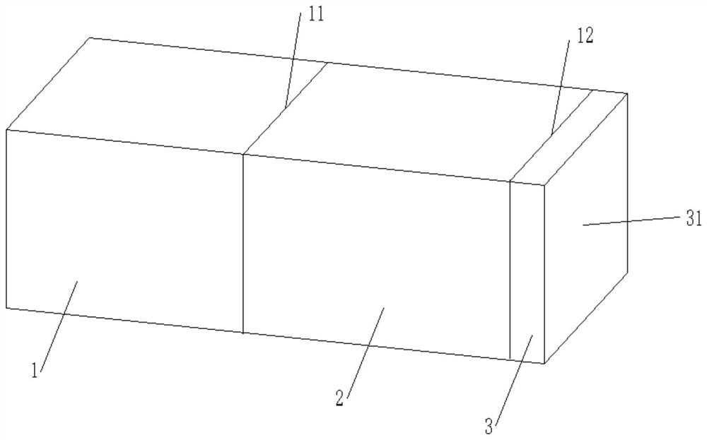
[0038] Please refer to figure 1 , the laser provided by Embodiment 1 of the present invention has a small size, a compact and regular structure, and facilitates miniaturization of the laser.

[0039] In this embodiment, the laser crystal includes a YAG crystal 3, a Cr:YAG crystal 2 and a Nd:YAG crystal 1, and these three crystals are sequentially bonded to form a small-sized passive Q-switched laser crystal.

[0040] Wherein, the second bonding surface 12 is formed between the YAG crystal 3 and the Cr:YAG crystal 2, the first bonding surface 11 is formed between the Cr:YAG crystal 2 and the Nd:YAG crystal 1, and the first bonding surface 11 and the second bonding surface The two bonding surfaces 12 are parallel to each other.

[0041] Wherein, the Nd:YAG crystal 1 is provided with a pump light incident end face 13 parallel to the first bonding face 11, and the YAG crystal 3 is provided with a laser emitting end face 31 parallel to the second bonding face 12, specifically , t...

Embodiment 2

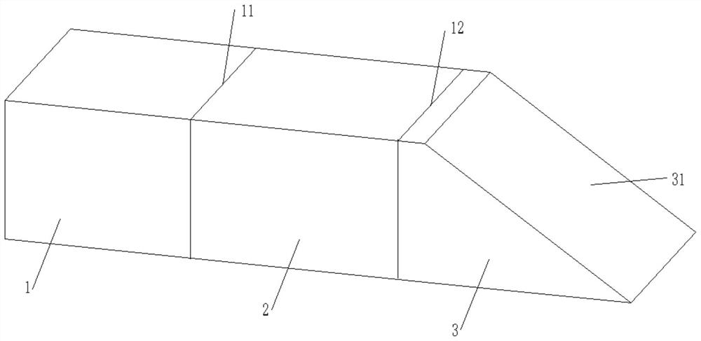
[0053] Please refer to figure 2 with image 3 , the laser crystal provided in Embodiment 2 is basically the same as the crystal structure of Embodiment 1, and the similarities will not be described in detail. The difference lies in:

[0054] In the second embodiment, the laser emitting end surface 31 and the second bonding surface 12 are set at a preset angle, optionally, the preset angle is 28°-32°, specifically, the preset angle is 30°.

[0055] In this embodiment, the pumping light is perpendicular to the pumping light incident end face 13 and enters the laser crystal. At this time, the laser emitting end face 31 is 60° to the pumping light incident direction. Therefore, when the laser is output from the laser emitting end face 31, a deflection.

[0056] In this embodiment, the laser emitting end surface 31 of the YAG crystal 3 is not coated with a film system, and one end of the YAG crystal 3 provided with the laser emitting end surface 31 is provided with an output mir...

Embodiment 3

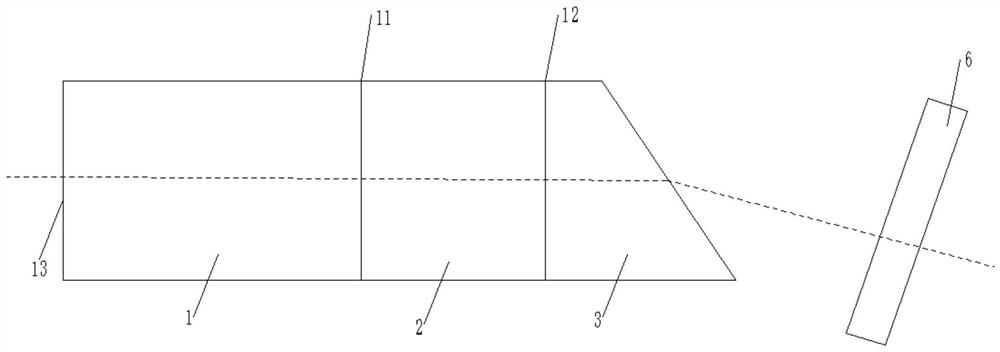
[0061] Please refer to Figure 4 with Figure 5 , the structure of a laser crystal provided in the third embodiment is basically the same as that in the second embodiment, and the similarities will not be repeated, but the difference is:

[0062] In the third embodiment, the laser emitting end surface 31 and the second bonding surface 12 are set at 30°, and the material of the output mirror 6 is YAG crystal 3. The output mirror 6 is used to output the laser after changing the laser output path. Specifically, the The output mirror 6 deflects the deflected laser path again, so that the final output path is consistent with the incident direction of the pump light.

[0063] In a specific embodiment, the output mirror 6 of YAG crystal material is wedge-shaped, and the output mirror 6 includes a deflection surface and an output surface, wherein the deflection surface is close to the laser exit end face 31 and is parallel to the laser exit end face 31, and the output surface is para...


PUM

PropertyMeasurementUnit
thicknessaaaaaaaaaa

Abstract

The invention discloses a laser crystal, a laser and a preparation method of hundred-picosecond laser, and the laser crystal comprises an Nd: YAG crystal, a Cr: YAG crystal and a YAG crystal. Two end surfaces of the Cr: YAG crystal are respectively bonded with the Nd: YAG crystal and the YAG crystal to form a first bonding surface and a second bonding surface. According to the technical scheme provided by the embodiment of the invention, while the thermal damage threshold of the crystal is improved, the compact structural design of the laser is realized, and the size miniaturization of the laser is realized.

Description

technical field [0001] The invention relates to the field of optical technology, in particular to a preparation method of a laser crystal, a laser and a picosecond laser. Background technique [0002] At present, laser beauty instruments generally use nanosecond (ns) lasers as light sources, but the application of nanosecond lasers still has some refractory pigmented diseases with ineffective curative effect, hyperpigmentation, depigmentation, and normal skin around skin lesions. There are limitations such as damage. [0003] With the continuous advancement of technology, picosecond laser has become one of the latest technologies applied to laser beauty. Compared with nanosecond lasers, picosecond lasers are more targeted to color bases due to their higher peak power and extremely short pulse width. They can effectively treat pigmented skin diseases, remove tattoos, and interact with human skin There is almost no heat loss during the process, so there is almost no thermal ...

Claims


Application Information

Patent Timeline
Patent Type & Authority Applications(China)
IPC IPC(8): H01S3/16H01S3/06
CPCH01S3/1643H01S3/0602H01S3/0615H01S2304/00
Inventor 涂玮王志敏许昌邹跃彭钦军
Owner TECHNICAL INST OF PHYSICS & CHEMISTRY - CHINESE ACAD OF SCI
Why Eureka
Try Eureka