Long-distance weak-coupling optical fiber coupler and application thereof

A technology of optical fiber coupler and optical fiber combiner, applied in the direction of coupling of optical waveguides, can solve the problems of reduction of guided wave, scattering, reflection, mode crosstalk, heat accumulation, etc., to reduce return loss and mode crosstalk, Prevent damage and destruction, eliminate the effect of cross-talk

Inactive Publication Date: 2014-07-09
JIANGSU SKYERALASER TECH +1
View PDF6 Cites 0 Cited by
  • Summary
  • Abstract
  • Description
  • Claims
  • Application Information

AI Technical Summary

Problems solved by technology

Scattering, reflections, and mode crosstalk can occur at this point
2 After the pump light enters the inner cladding of the active fiber, it crosstalks with the signal light. After passing through the reflection point, the reflected light of the signal light enters the optical path of the pump light, and thus enters the inside of the pump semiconductor laser. Will cause the pump laser to work unstable, damaged, or burned
This is extremely detrimental to the work of fiber lasers and fiber amplifiers
3 The optical power density of the optical fiber combiner at the beam combining point and the bifurcation connection is high, and the heat accumulates. Long-term work is easy to cause heat, which causes the waveguide waveguide to change, thereby reducing or even destroying the optical fiber combiner. work performance

Method used


Image

  • Long-distance weak-coupling optical fiber coupler and application thereof
  • Long-distance weak-coupling optical fiber coupler and application thereof
  • Long-distance weak-coupling optical fiber coupler and application thereof

Examples


Embodiment 1

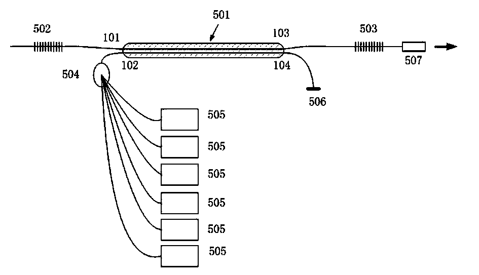
[0022] like image 3 Shown is a schematic structural diagram of the first fiber laser using the fiber coupler of the present invention. A fiber laser, using 6 independent semiconductor pump lasers 505, combined into a bundle through a 6 x 1 fiber combiner 504, and then enters the port 102 of the second optical fiber 202 of the fiber coupler 501 of the present invention. The first optical fiber 201 is an active optical fiber with an inner cladding 402 and a core 401, the core portion of which is doped with a rare earth element at a relatively low concentration. The first optical fiber 201 is engraved with fiber gratings on both sides of the coupling part as light reflectors 502 and 503, which constitute a laser resonator of the desired wavelength. The pump laser light is weakly coupled per unit length through the fiber coupler of the present invention, and the pump laser light in the optical fiber 202 is coupled into the inner cladding of the optical fiber 201 . The inner cla...

Embodiment 2

[0024]As shown in FIG. 4 , it is a schematic structural diagram of the second fiber laser using the fiber coupler of the present invention. A semiconductor laser is used as the seed light source 508, and the pulsed laser output from it is pre-amplified through the pre-optical amplifier 510, and then enters the port 101 of the first optical fiber of the fiber coupler of the present invention. A cladding optical power stripper for double-clad fiber is already included inside the preamplifier. The pumping source uses 6 independent semiconductor pumping lasers 505, which are combined into one bundle through a 6 x 1 fiber combiner 504, and then enter the port 2 of the second optical fiber of the fiber coupler 501 of the present invention. The first optical fiber 201 is an active optical fiber with an inner cladding 402 and a core 401, the core portion of which is doped with a rare earth element at a relatively low concentration. The first optical fiber 201 does not require fiber g...


PUM


Abstract

A long-distance weak-coupling optical fiber coupler comprises two optical fibers (201 and 202), a coupling area (501) and four terminals (101, 102, 103 and 104). The two optical fibers (201 and 202) are arranged in parallel at the equal interval and share a common outer cover layer (301). The two optical fibers can generate weak coupling in the outer cover layer (301) to form the coupling area. The four terminals (101, 102, 103 and 104) are arranged outside the outer cover layer (301). The long-distance weak-coupling optical fiber coupler is characterized in that the length of the coupling area (501) is between 2 meters and 20 meters, and the horizontal distance between the centers of the two optical fibers is between 100 micrometers and 500 micrometers. The long-distance weak-coupling optical fiber coupler eliminates a traditional method using an optical fiber combiner to generate pumping laser to couple an inner cover layer of an active double-cover-layer optical fiber and remarkably improves performance.

Description

technical field [0001] The invention relates to an optical fiber coupler, in particular to a long-distance weakly coupled optical fiber coupler. Background technique [0002] We know that fiber lasers have developed rapidly in recent years. Its types include fiber-optic pulsed lasers, fiber-optic high-power CW lasers, and fiber-optic high-power quasi-CW lasers. These fiber lasers all need to couple the pump laser light into the inner cladding of the active fiber for optical amplification. [0003] The current method of coupling the pump laser light into the inner cladding of the active fiber is to use a fiber combiner, which is divided into two types: N x 1 and N +1 x 1. The former couples N beams of pump light into the inner cladding of the active fiber; the latter couples N beams of pump light into the inner cladding of the active fiber while keeping the signal light transmission of the central core unchanged. In actual use, the effect is obviously deviated from the ide...

Claims


Application Information

Patent Timeline
Patent Type & Authority Applications(China)
IPC IPC(8): G02B6/42
Inventor 周胜李丰谈根林
Owner JIANGSU SKYERALASER TECH
Why Eureka
Try Eureka