Winding technology of transformer and transformer manufactured with winding technology

A transformer and wire winding technology, applied in the field of transformers, can solve problems such as inter-turn short circuit, affecting the life of the transformer, enameled wire breakage, etc., and achieve the effects of increasing reliability and life, high production efficiency, and low defect rate

Active Publication Date: 2016-10-12
DONGGUAN DAZHONG ELECTRONICS
View PDF6 Cites 0 Cited by
  • Summary
  • Abstract
  • Description
  • Claims
  • Application Information

AI Technical Summary

Problems solved by technology

In the case of multi-strand wires, the starting end of the twisted wires cannot be completely twisted, otherwise it will be broken due to excessive twisting. Generally, there will be a small part of the tail end that is not twisted and is in a loose state. However, in the follow-up In the process of winding with an automatic winding machine, due to the high speed of the winding machine, the loose part of the twisted wire (with a thread end) is easily taken up by the subsequent winding, and even brought from the bottom to the middle layer, it is very easy to cause inter-turn short circuit after the transformer works for a long time, or cause ignition and burnout at the moment of power-on due to voltage difference, thus affecting the life of the transformer
[0003] In order to solve this pr

Method used


Image

  • Winding technology of transformer and transformer manufactured with winding technology
  • Winding technology of transformer and transformer manufactured with winding technology
  • Winding technology of transformer and transformer manufactured with winding technology

Examples


Embodiment Construction

[0038] The invention is further described in conjunction with the following examples.

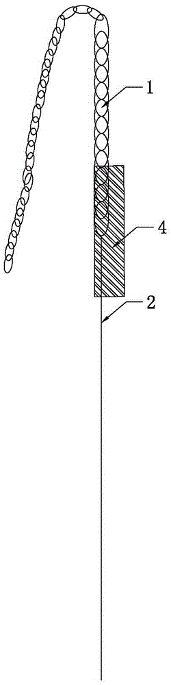
[0039] The transformer of this embodiment includes a rubber core 3, the rubber core 3 includes a side wall, and the side wall is provided with a wire slot, and the winding includes a primary winding, and the primary winding is an enameled wire (that is, a single-strand winding Wire 2), the multi-strand enameled wire at the incoming end of the primary winding wire is twisted into a strand 1, and the winding process includes the following steps:

[0040] 1) if figure 1 As shown, use the first layer of insulating tape 4 to wrap the twisted part of the twisted wire 1;

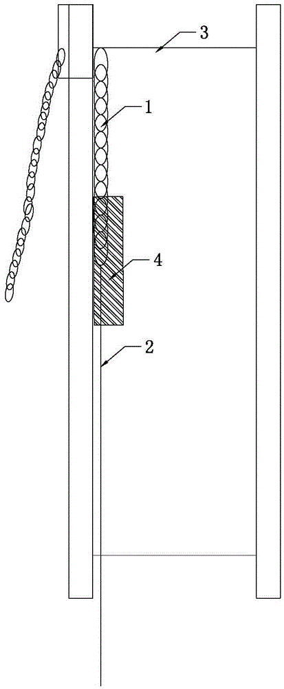
[0041] 2) passing the twisted wire 1 from the outside of the wire inlet slot through the inside of the wire inlet slot;

[0042] 3) if figure 2 As shown, the twisted wire 1 is pressed on the inner side of the side wall of the rubber core 3;

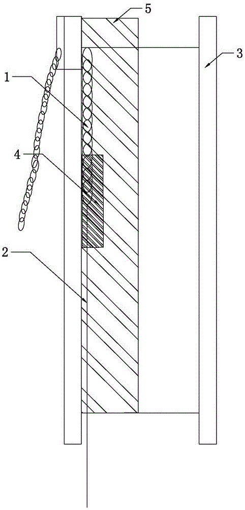
[0043] 4) if image 3 As shown, a second layer of insulating tape 5 is used to f...


PUM


Abstract

The invention discloses a winding technology of a transformer and the transformer manufactured with the winding technology, and relates to the technical field of transformers. The winding technology of the transformer includes the steps that stranded parts of stranded wires are wrapped with first insulation tape; the stranded wires penetrate through the inner side of a wire feeding groove from the outer side of the wire feeding groove; the stranded wires are pressed on the inner side of the side wall of a rubber core; the stranded wires located on the inner side of the wire feeding groove are fixed on the rubber core through second insulation tape. The hidden danger problem of incompact parts of the stranded wires and the hidden danger problem of inter-turn short circuits are solved, the previous problem that as the tape is not fixed and also moves when a winding machine rotates, winding wires are broken is solved, the reliability of the transformer is improved, and the service life of the transformer is prolonged; meanwhile, the manufacturing efficiency of the transformer is higher, and the reject ratio is lower.

Description

technical field [0001] The invention relates to the technical field of transformers, in particular to a transformer winding process and a transformer made by the winding process. Background technique [0002] In power transformer products, very thin enameled wires are often used in the primary stage. At this time, multi-strand wires are required at the inlet and outlet ends to prevent the enameled wire from breaking during the winding process and soldering process. In the case of multi-strand wires, the starting end of the twisted wires cannot be completely twisted, otherwise it will be broken due to excessive twisting. Generally, there will be a small part of the tail end that is not twisted and is in a loose state. However, in the follow-up In the process of winding with an automatic winding machine, due to the high speed of the winding machine, the loose part of the twisted wire (with a thread end) is easily taken up by the subsequent winding, and even brought from the bo...

Claims


Application Information

Patent Timeline
IPC IPC(8): H01F41/07H01F41/12
CPCH01F41/125
Inventor 李成李正中
Owner DONGGUAN DAZHONG ELECTRONICS
Why Eureka
Try Eureka