Drying sintering furnace and drying sintering method

A technology for sintering furnaces and sintering zones, applied in the direction of furnaces, furnace components, furnace types, etc., can solve problems such as difficulty in ensuring the temperature in the temperature zone, temperature inconsistency, etc., achieve easy implementation, prevent waste gas pollution control, and improve stability Effect

Active Publication Date: 2016-10-12
FOLUNGWIN AUTOMATIC EQUIP CO LTD
View PDF4 Cites 13 Cited by
  • Summary
  • Abstract
  • Description
  • Claims
  • Application Information

AI Technical Summary

Problems solved by technology

[0003] The currently used solar silicon wafer sintering furnaces generally have multiple temperature zones, and each temperature zone is equipped with a heating tube and a temperature control device to maintain a constant temperature in each temperature zone. , it is difficult to guarantee the temperature of the temperature zone

Method used


Image

  • Drying sintering furnace and drying sintering method
  • Drying sintering furnace and drying sintering method
  • Drying sintering furnace and drying sintering method

Examples


Embodiment Construction

[0036] The present invention will be further described below according to the accompanying drawings and specific embodiments, but the embodiments of the present invention are not limited thereto.

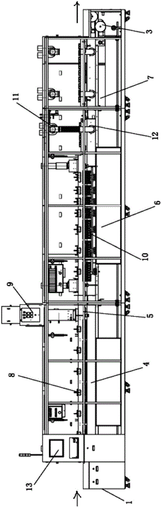
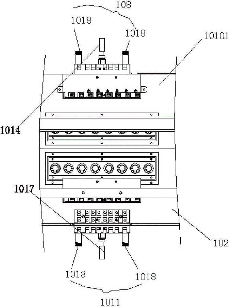
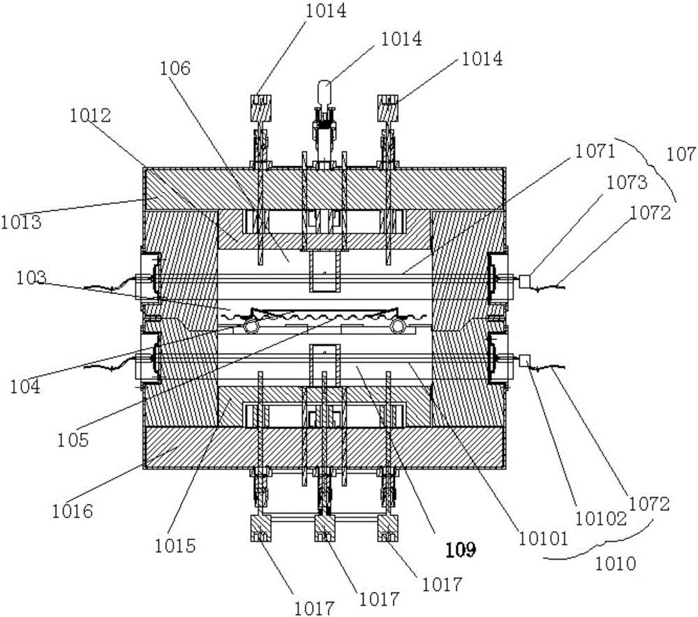
[0037] like figure 1 , figure 2 , image 3 , Figure 4 and Figure 5 As shown, a drying and sintering furnace includes a conveying platform 1. The upper plane of the conveying platform 1 is provided with a conveying belt 105. The conveying belt 105 is driven by two rollers 3 controlled by a single motor for transportation. The conveying platform 1 is from the feed end to the The discharge end is provided with a silicon wafer preheating zone 4, a waste gas combustion zone 5, a sintering zone 6 and a silicon wafer cooling zone 7 in sequence, and a plurality of drying preheating furnaces 8 are arranged at intervals in the silicon wafer preheating zone 4, and a plurality of The temperature of the drying preheating furnace 8 gradually rises, the waste gas combustion zone 5 is provid...


PUM


Abstract

The invention discloses a drying sintering furnace which comprises a conveying table. A conveying belt is arranged on the upper plane of the conveying table. A single motor controls two stick wheels to drive the conveying belt to carry out transporting. The conveying table is successively provided with a silicon slice preheating zone, a waste gas combustion zone, a sintering zone and a silicon slice cooling zone from the feeding end to the discharging end. A number of drying preheating furnaces are arranged in the silicon slice preheating zone at intervals. The temperature of a number of drying preheating furnaces gradually rises. A combustion tower is arranged in the waste gas combustion zone. A number of sealed sintering furnaces whose temperature is independently controlled are arranged at intervals in the sintering zone. The temperature of each sintering furnace is the same. A number of blowing devices and suction devices are arranged at intervals in the silicon slice cooling zone. A control device is arranged before or after the conveying table. According to the invention, the structure is simple; the temperature of each sintering temperature zone is balanced; and harmful waste gas is sufficiently combusted.

Description

technical field [0001] The invention relates to solar silicon wafer sintering equipment, in particular to a drying and sintering furnace. Background technique [0002] Solar cells are mainly composed of silicon wafers, and semiconductor P-N junctions are formed on high-purity silicon wafers. The processing includes cleaning, drying, diffusion, etching, spraying, printing and sintering. [0003] The currently used solar silicon wafer sintering furnaces generally have multiple temperature zones, and each temperature zone is equipped with a heating tube and a temperature control device to maintain a constant temperature in each temperature zone. , it is difficult to guarantee the temperature in the temperature zone. Contents of the invention [0004] The object of the present invention is to address the above-mentioned defects of the prior art, and provide a drying and sintering furnace with a simple structure that can ensure the temperature balance of each sintering tempera...

Claims


Application Information

Patent Timeline
Patent Type & Authority Applications(China)
IPC IPC(8): H01L31/18H01L21/67F27B9/02F27B9/06F27B9/20F27D17/00
CPCF27B9/02F27B9/063F27B9/20F27D17/008H01L21/67098H01L31/1804Y02E10/547Y02P70/50
Inventor 苏金财冼志军王军涛
Owner FOLUNGWIN AUTOMATIC EQUIP CO LTD
Why Eureka
Try Eureka