
Feedback control-based closed-loop power control system and method for CO2 radio frequency excited laser

A closed-loop power control and feedback control technology, which is applied to lasers, laser components, phonon exciters, etc., can solve problems such as poor control effects and unstable output power, and achieve easy power adjustment, improved linearity, The effect of improving the output optical power stability

Inactive Publication Date: 2016-10-12
北京大威激光科技有限公司
View PDF4 Cites 1 Cited by
  • Summary
  • Abstract
  • Description
  • Claims
  • Application Information

AI Technical Summary

Problems solved by technology

[0013] The technical problem to be solved by the present invention is to provide a closed-loop power control system and method for CO2 radio frequency lasers based on feedback control. good question

Method used


Image

  • Feedback control-based closed-loop power control system and method for CO2 radio frequency excited laser
  • Feedback control-based closed-loop power control system and method for CO2 radio frequency excited laser
  • Feedback control-based closed-loop power control system and method for CO2 radio frequency excited laser

Examples


Embodiment 1

[0070] Such as figure 1 As shown, the present embodiment proposes a CO2 RF laser closed-loop power control system based on feedback control, and the system includes:

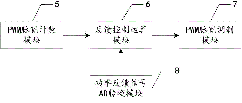
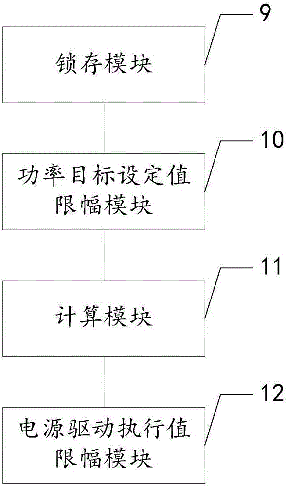
[0071] The feedback control module 1 is used to receive the power control input PWM signal input from the external control input terminal and the power feedback signal output by the CO2 laser power detection module 4, and output the excitation power input signal to the radio frequency excitation power supply 2 after control calculation.

[0072] The feedback control module 1 is implemented based on CPLD / FPGA or DSP, and is responsible for receiving the power control signal input from the external control input terminal, generally a PWM pulse width modulation signal, and the power feedback signal from the CO2 laser power detection module 4, generally an analog voltage signal , after the internal control algorithm operation, the input signal of the excitation power supply is given to the RF power supply. The inpu...

Embodiment 2

[0099] Such as Figure 5 As shown, the present embodiment proposes a CO2 RF laser closed-loop power control method based on feedback control, the method comprising:

[0100] The feedback control step is used to receive the power control input PWM signal and the power feedback signal input by the external control input terminal, and output the excitation power input signal after the control operation;

[0101] The feedback control step is implemented based on CPLD / FPGA or DSP, and is responsible for receiving the power control signal input by the external control input terminal, generally a PWM pulse width modulation signal, and the power feedback signal from the CO2 laser power detection step, generally an analog voltage The signal, through the control algorithm operation, outputs the input signal of the excitation power supply. The input signal of the excitation power supply is still a PWM pulse width modulation signal. CO2 RF lasers have different optimization requirements...


PUM


Abstract

The invention relates to a CO based on feedback control 2 A radio frequency laser closed-loop power control system and method. involving CO 2 RF laser power control field. The purpose is to solve the current CO 2 The RF laser power control adopts the open-loop power control method to cause unstable output power and poor control effect. The present invention proposes to achieve CO 2 The closed-loop and negative feedback power control of RF lasers can greatly improve the CO 2 The stability of the output optical power of the RF laser can meet some applications that have higher requirements on the stability of the optical power. Feedback control also improves CO 2 The power control linearity of RF lasers makes power adjustments easier to implement. And by feedback CO 2 The fluctuation of the output power of the RF laser is suppressed to achieve a high degree of stability of the laser output power.

Description

technical field [0001] The invention relates to the field of CO2 radio frequency laser power control. Background technique [0002] In general laser processing applications, such as laser marking, laser cutting, etc., the fluctuation range of laser power under open-loop control mode is acceptable, but in some industries that require high precision of laser power, such as medical treatment and optical fiber fusion Processing and other fields can not meet the requirements. In medical applications, CO2 laser can be used to destroy and kill tumor tissue. In order to prevent damage to normal tissue, the laser power must be strictly and stably controlled. In optical fiber processing applications such as optical fiber fusion splicing and tapering, only by stably controlling the power of the CO2 laser for heating can the processing effect be guaranteed. [0003] Currently widely used CO2 RF lasers mostly use PWM power control to adjust the output power of the laser. Generally, by...

Claims


Application Information

Patent Timeline
Patent Type & Authority Applications(China)
IPC IPC(8): H01S3/104
CPCH01S3/104
Inventor 庞海波
Owner 北京大威激光科技有限公司
Learn More