Turbonator cooling system provided with water cooling stator and inner fan type rotor

A turbogenerator and internal fan technology, applied in the direction of cooling/ventilation devices, electrical components, electromechanical devices, etc., can solve the problems of high rotor core and rotor winding temperature, unreasonable ventilation design, etc., to improve the safety and stability of operation The effect of ability, ability to lower temperature, and ability to increase heat

Active Publication Date: 2016-10-12
HARBIN UNIV OF SCI & TECH
View PDF8 Cites 10 Cited by
  • Summary
  • Abstract
  • Description
  • Claims
  • Application Information

AI Technical Summary

Problems solved by technology

[0004] The purpose of the present invention is to provide a turbogenerator cooling system with a water-cooled stator and an internal fan-type rotor to solve the problem of excessive temperature of the stator core, rotor core and rotor winding caused by unreasonable ventilation design in the stator-rotor area of ​​the turbogenerator. Therefore, the utilization rate of the cooling fluid in the stator and rotor area of ​​the turbogenerator can be improved, the temperature of the stator core, rotor core and rotor winding can be effectively reduced, and the long-term stable operation ability of the turbogenerator can be improved.

Method used


Image

  • Turbonator cooling system provided with water cooling stator and inner fan type rotor
  • Turbonator cooling system provided with water cooling stator and inner fan type rotor
  • Turbonator cooling system provided with water cooling stator and inner fan type rotor

Examples


specific Embodiment approach 1

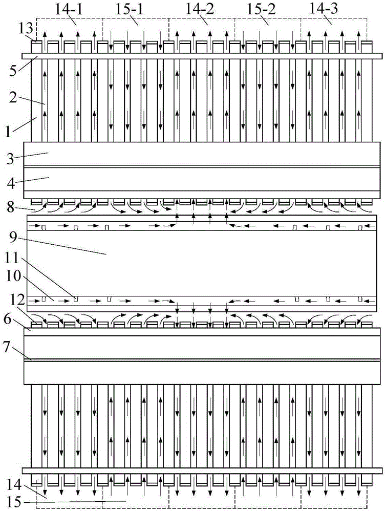
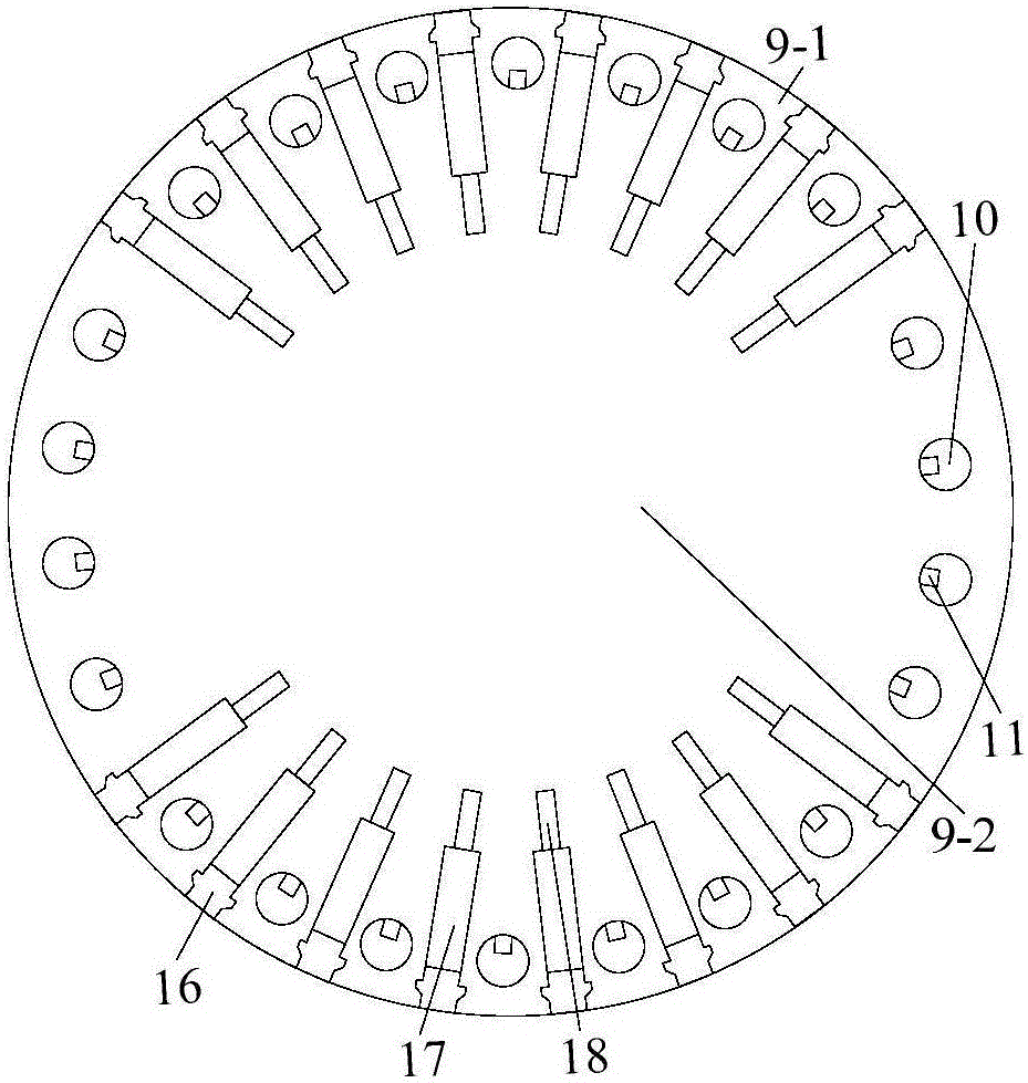
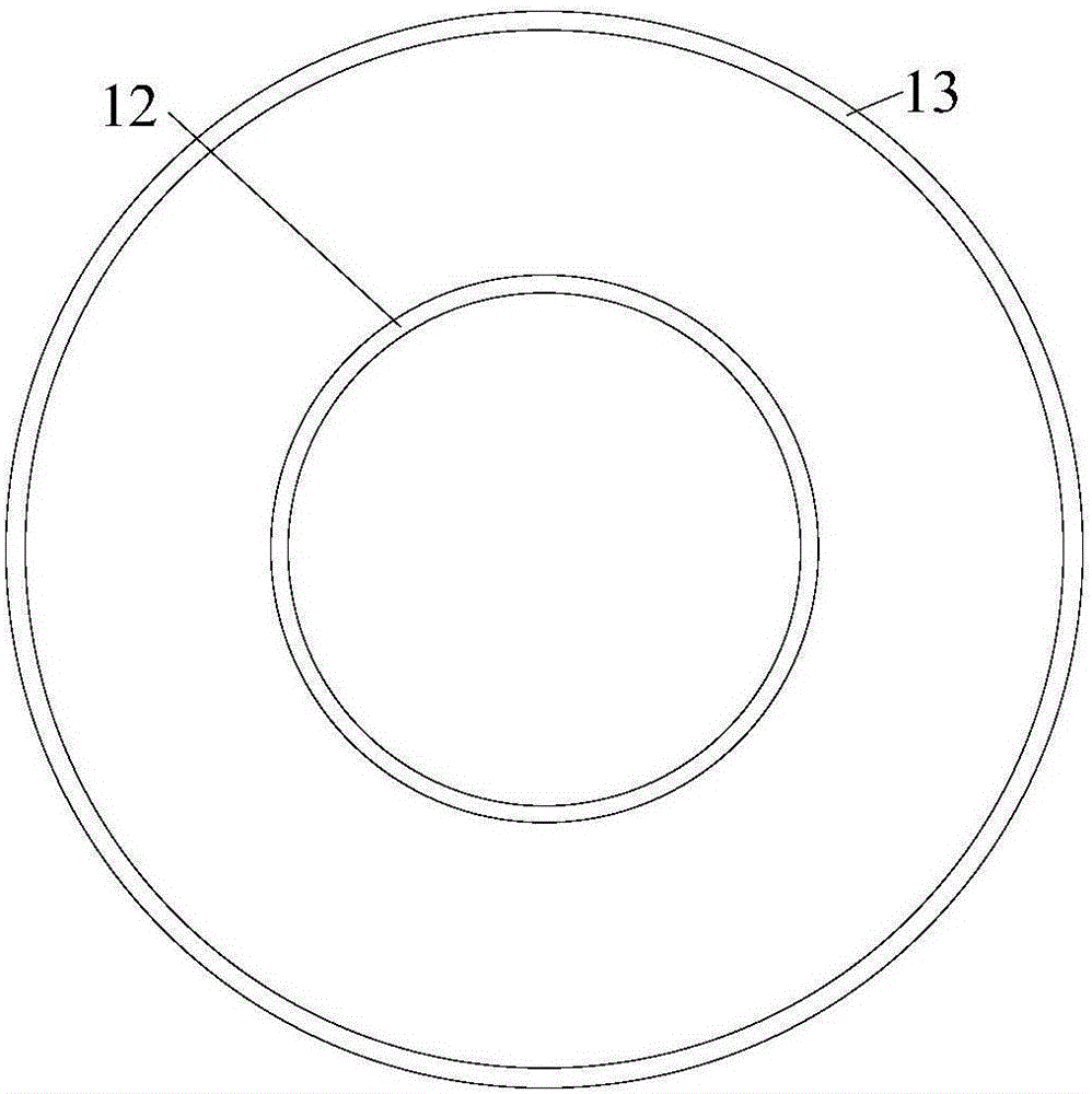
[0026] Specific implementation mode one: combine figure 1 , figure 2 , image 3, Figure 4 with Figure 5 To illustrate this embodiment, a turbogenerator cooling system with a water-cooled stator and an internal fan rotor of the present invention includes a stator, a rotor 9 and an air gap 8 between the stator and the rotor, the stator includes a stator core segment 1 , stator upper layer winding 4 and stator lower layer winding 3 arranged on stator core section 1, stator interlayer insulation 7 arranged between stator upper layer winding 4 and stator lower layer winding 3, stator slot wedge 6, positioning rib 5, the stator The core segments 1 are arranged at equal intervals along the axial direction, and stator radial ventilation grooves 2 are arranged between adjacent stator core segments 1, and the stator radial ventilation grooves 2 communicate with the air gap 8, and also include stator outer surrounding water channels 13 and the stator inner surrounding waterway 12,...

specific Embodiment approach 2

[0032] Specific implementation mode two: combination figure 1 , figure 2 , image 3 , Figure 4 with Figure 5 , The difference between this embodiment and Embodiment 1 is that all the stator inner surrounding water channels 12 in the first stator hot air zone 14-1, the stator second hot air zone 14-2 and the stator third hot air zone 14-3 In series with each other, that is, the stator inner surrounding water channels of the three hot air zones are connected in series; all the stator outer surrounding water channels in the first stator hot air zone 14-1, the stator second hot air zone 14-2 and the stator third hot air zone 14-3 are connected in series. The water channels 13 are connected in series, that is, the water channels surrounding the stators in the three hot air zones are connected in series. The stator inner surrounding waterway 12 of the first stator cold wind zone 15-1 is connected in series with the stator inner surrounding waterway 12 of the stator second col...

specific Embodiment approach 3

[0033] Specific implementation mode three: combination figure 1 , figure 2 , image 3 , Figure 4 with Figure 5 The difference between this embodiment and Embodiment 1 is that the stator inner surround Type water pipes 12-2 are connected in series respectively; the stator outer surrounding water pipes 13-2 in each wind area of ​​the stator first hot air area 14-1, the stator second hot air area 14-2 and the stator third hot air area 14-3 respectively connected in series; the stator inner surrounding water pipes 12-2 in each wind region of the first stator cold wind region 15-1 and the stator second cold wind region 15-2 are respectively connected in series; the stator first cold wind region 15-1 and the stator second cold wind region The stator outer surrounding water pipes 13-2 in each wind zone of the cold wind zone 15-2 are respectively connected in series. In the stator hot air zone 14, cooling water with a flow rate of 1.2m / s passes through all the stator inner sur...


PUM


Abstract

The invention discloses a turbonator cooling system provided with a water cooling stator and an inner fan type rotor and relates to a field of motors. According to the invention, by adding an in-stator loop type water channel and an out-of-stator loop type water channel at a tooth top part and a yoke back part of an iron core segment of the stator respectively, arranging a rotor axial ventilating duct in rotor teeth and arranging rotor self-cooling fan blades in the rotor axial ventilating duct, the heat dissipation capability of a rotor area and a stator area is enhanced effectively, the utilization rate of cooling fluid in the turbonator is improved, the highest temperature of the stator area and the stator area are reduced substantially and the capability of safe and stable operation of the turbonator is improved.

Description

Technical field: [0001] The invention relates to a turbogenerator cooling system with a water-cooled stator and an internal fan-type rotor, belonging to the field of electric machines. Background technique: [0002] The loss of traditional stator and rotor cores is large, the ventilation and cooling effect is poor, and the heat generated cannot be taken away by the surrounding cooling fluid in time, resulting in high temperature of the stator and rotor cores. In order to limit the temperature of the components in the stator and rotor area of ​​the turbogenerator within the allowable temperature rise range of the generator insulation material, the loss of each component of the turbogenerator needs to be absorbed by the surroundings in the form of heat during rated operation or advanced phase operation. The flowing cooling fluid is taken away, thereby achieving the purpose of reducing the temperature of each component of the turbogenerator. [0003] With the increase of the u...

Claims


Application Information

Patent Timeline
Patent Type & Authority Applications(China)
IPC IPC(8): H02K1/20H02K9/19H02K1/32H02K9/06
CPCH02K1/20H02K1/32H02K9/06H02K9/19
Inventor 韩继超戈宝军于长胜杨帆赵洪森李伟力
Owner HARBIN UNIV OF SCI & TECH
Why Eureka
Try Eureka