

High-frequency high-voltage power supply for capacitive loads
A high-frequency high-voltage power supply and capacitive load technology, which is applied to electrical components, output power conversion devices, and AC power input to AC power output. It can solve the problems of lack of dedicated capacitive load high-frequency high-voltage device power supply, etc. Achieve the effect of preventing oscillation and reducing stray inductance
- Summary
- Abstract
- Description
- Claims
- Application Information
AI Technical Summary
Problems solved by technology
Method used
Image

Examples
Embodiment Construction
[0032] In order to illustrate the embodiments and technical solutions of the present invention more clearly, the technical solutions of the present invention will be described in more detail below in conjunction with the accompanying drawings and embodiments. Obviously, the described embodiments are part of the embodiments of the present invention, not all of them. Example. Based on the embodiments of the present invention, all other embodiments obtained by persons of ordinary skill in the art without making creative efforts fall within the protection scope of the present invention.
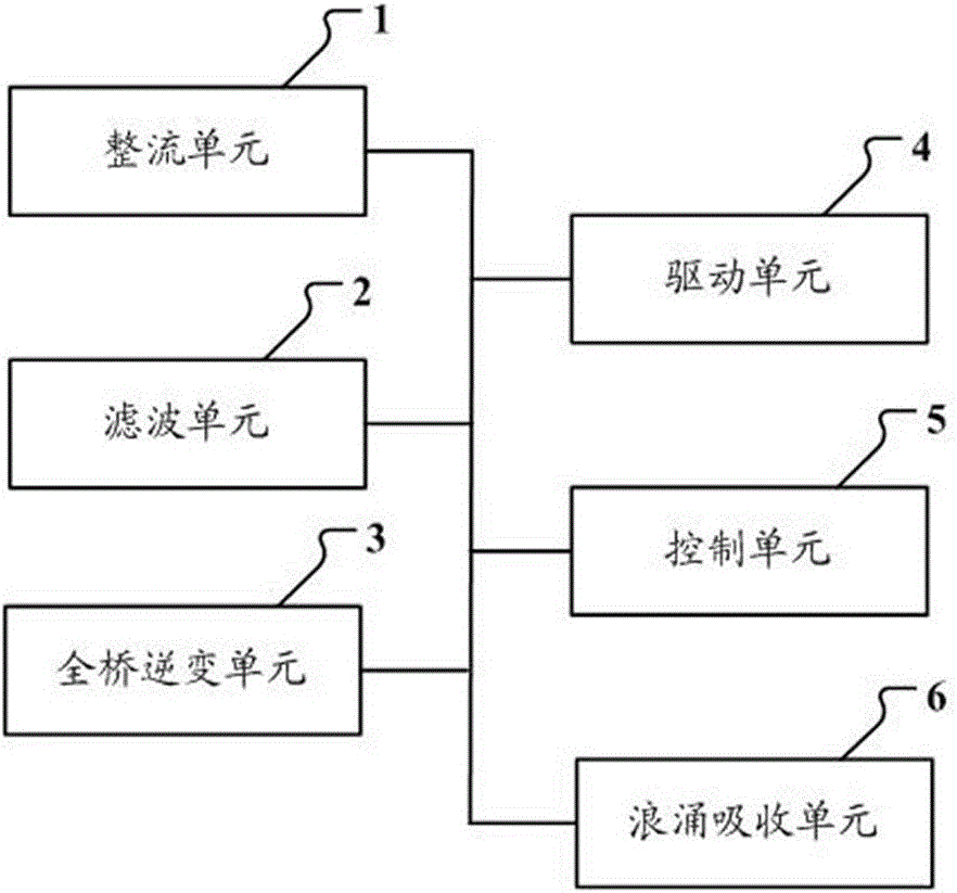
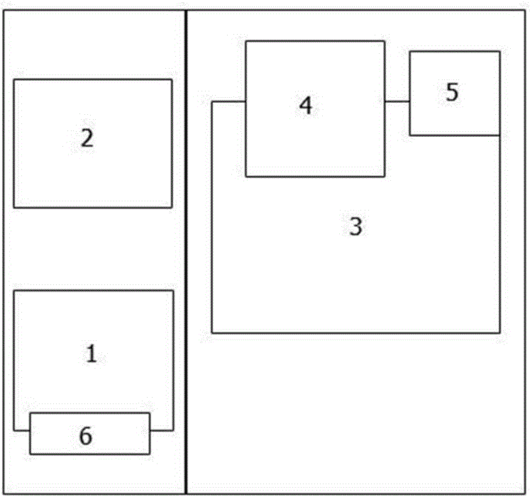
[0033] see figure 1 , is a schematic structural diagram of a capacitive load high-frequency high-voltage power supply provided in Embodiment 1 of the present invention, wherein a rectifier unit 1, a filter unit 2, a full-bridge inverter unit 3, a drive unit 4, a control unit 5 and a surge absorption unit 6;
[0034] The rectifying unit 1, the filtering unit 2, and the full-bridge inverter unit 3...
PUM
 Abstract
Description
Claims
Application Information