Check patentability & draft patents in minutes with Patsnap Eureka AI!

Method and apparatus for controlling a hybrid energy storage system

A technology for energy storage systems and control equipment, applied in the field of hybrid energy storage systems, capable of solving problems such as inability to easily apply hybrid energy storage systems

Active Publication Date: 2016-10-12
ABB (SCHWEIZ) AG
View PDF6 Cites 5 Cited by
  • Summary
  • Abstract
  • Description
  • Claims
  • Application Information

AI Technical Summary

Problems solved by technology

[0005] Although the above approach is effective in the limited context in which it is applied, it cannot be easily adapted to hybrid energy storage systems involving multiple types of energy storage units
In addition, the conventional methods described above are not suitable for hybrid energy storage systems involving distributed loads that may be located on different buses, where local bus measurements may be critical for optimal operation of the various energy storage units

Method used


Image

  • Method and apparatus for controlling a hybrid energy storage system
  • Method and apparatus for controlling a hybrid energy storage system
  • Method and apparatus for controlling a hybrid energy storage system

Examples


Embodiment Construction

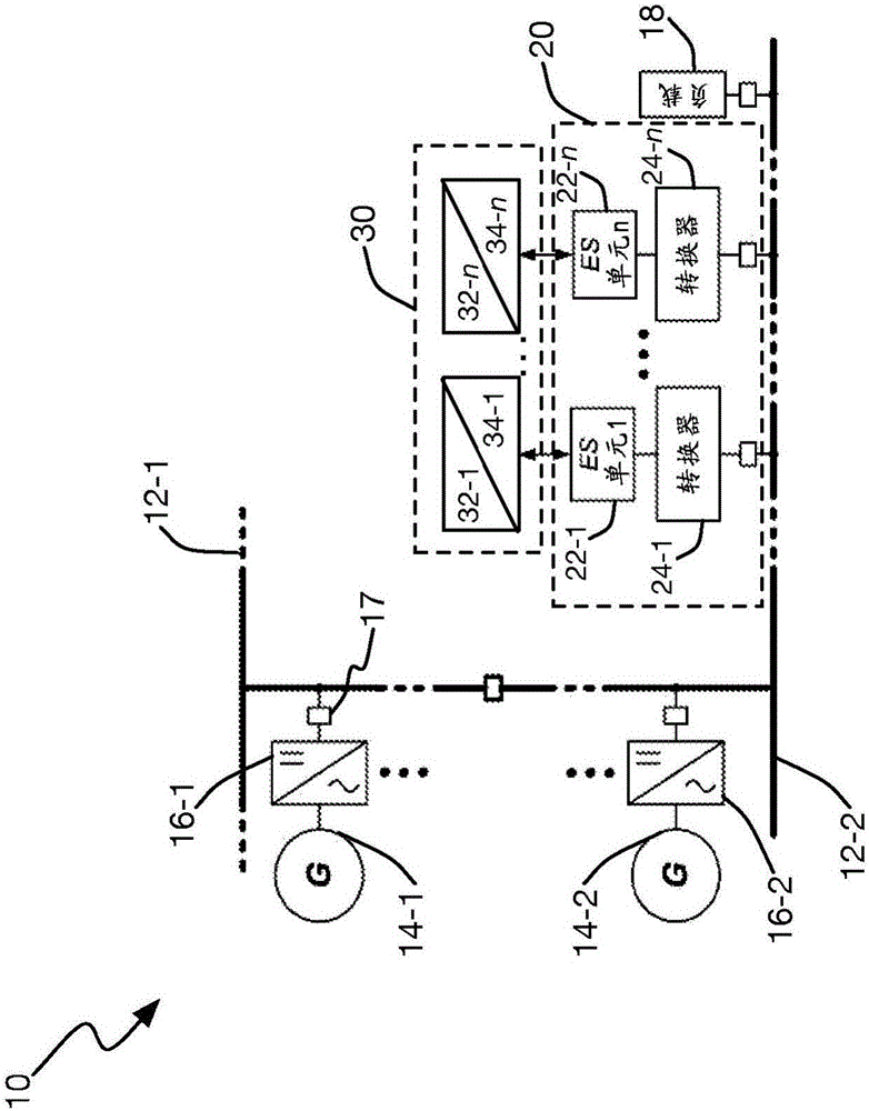
[0020] figure 1 A hybrid power grid or system 10 is shown, which includes one or more electrical buses 12, such as DC buses 12-1,21-2. The hybrid power grid 10 also includes one or more generating sources 14 and corresponding coupling circuits 16 for coupling the generating sources 14 to the corresponding electrical bus 12, for example, the generating source 14-1 is coupled to the bus through the coupling circuit 16-1 12-1, and the source 14-2 is coupled to the bus 12-2 through the coupling circuit 16-2. For a given exemplary case where the electrical bus 12 is a DC bus, the one or more coupling circuits 16 each include an AC / DC converter. The coupling circuit 16 can be connected to its corresponding electrical bus 12 through a circuit breaker 17.

[0021] Note that, for the sake of clarity, any of the reference numerals 12, 14, and 16 may be used without a suffix to indicate a singular or plural number when a suffix is ​​not required. In the remainder of this article, a simila...


PUM


Abstract

In one aspect of the teachings herein, a control apparatus (30) and corresponding control method use per-unit filtering in a plurality of power-sharing controllers (32 1-n), to obtain a power-sharing command signal for respective ones among a plurality of different energy storage units (22 1-n) in a hybrid energy storage system. The hybrid energy storage system includes two or more types of energy storage units and the power-sharing command signal for each energy storage unit is obtained by filtering an input signal using a filter having a filter response that is tailored to the energy storage characteristics of the energy storage unit. The input signal reflects load variations on the electrical grid (10) and may be locally generated or provided by a remote node. While the power-sharing control loops used for each energy storage unit advantageously may be the same in terms of architecture and implementation, each such loop uses tailored, dedicated filtering and, possibly, individualized values of one or more other control parameters, so that each energy storage unit is operated in a manner that complements its energy storage characteristics.

Description

Technical field [0001] The present invention relates generally to energy storage systems, and in particular to hybrid energy storage systems involving two or more types of energy storage units. Background technique [0002] Hybrid power grids, including localized on-board power grids used in marine vehicles, represent areas of increased interest and rapid development, especially because these power grids can significantly reduce greenhouse gases due to their potentially higher efficiency emission. In this context, "hybrid" power grids include one or more generation sources and one or more energy storage systems. The one or more energy storage systems provide a mechanism that stores the energy generated by the one or more sources and / or is obtained through one or more regeneration processes, and stores some or all of the energy It is provided to the grid, for example, to meet peak load requirements and / or to eliminate the difference in demand imposed on the one or more sources. ...

Claims


Application Information

Patent Timeline
IPC IPC(8): H02J1/10H02J1/14H02J3/32H02J3/46H02J7/34
CPCH02J1/10H02J1/14H02J1/102H02J7/345
Inventor 梁嘉祺亓丽
Owner ABB (SCHWEIZ) AG
Features
  • R&D
  • Intellectual Property
  • Life Sciences
  • Materials
  • Tech Scout
  • Unparalleled Data Quality
  • Higher Quality Content
  • 60% Fewer Hallucinations
Learn More