Sterilization unit for packaging material

A technology for sterilization devices and packaging materials, which is applied in the directions of packaging sterilization, electrical equipment construction parts, disinfection, etc., can solve the problems of inapplicable insulation technology and unsuitable insulation technology, and achieve improved electrical insulation performance and low weight. Effect

Active Publication Date: 2019-11-08
TETRA LAVAL HLDG & FINANCE SA
View PDF7 Cites 0 Cited by
  • Summary
  • Abstract
  • Description
  • Claims
  • Application Information

AI Technical Summary

Problems solved by technology

Furthermore, known insulation technologies are often not suitable for the requirements of the packaging industry
For example, insulation techniques that include hazardous materials or that may damage or contaminate materials that must be sterilized (such as packaging materials for food, liquids, or pharmaceuticals) are not suitable for use in such environments

Method used


Image

  • Sterilization unit for packaging material
  • Sterilization unit for packaging material
  • Sterilization unit for packaging material

Examples


Embodiment Construction

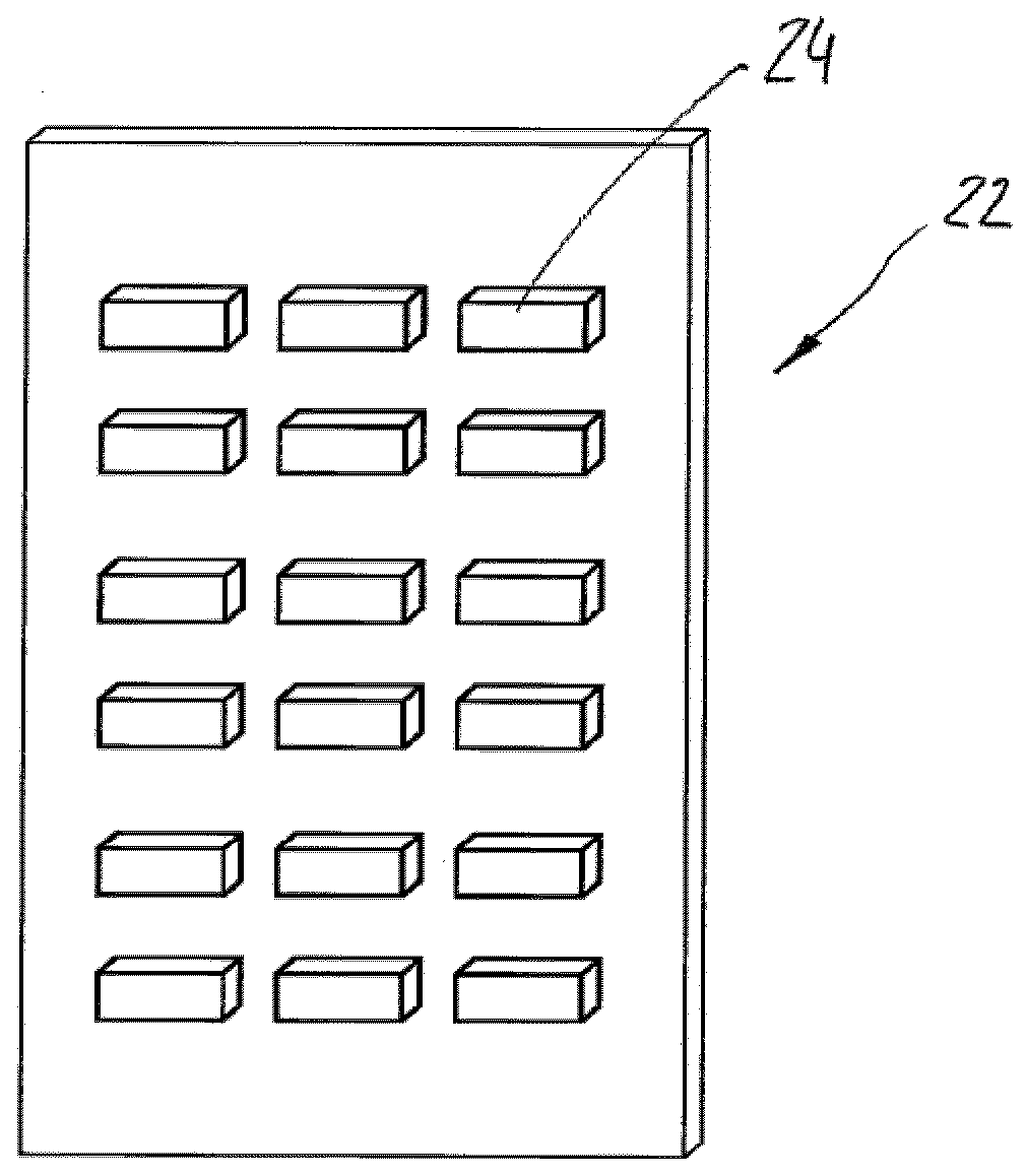
[0049] now refer to Figure 1a , showing the electronic assembly 22 . Electronic assembly 22 includes a plurality of electronic components 24 .

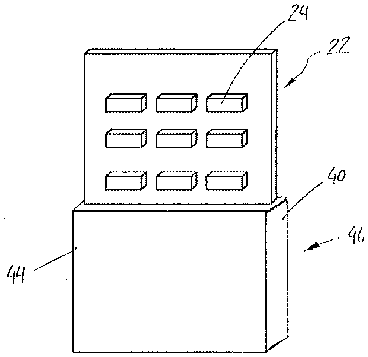
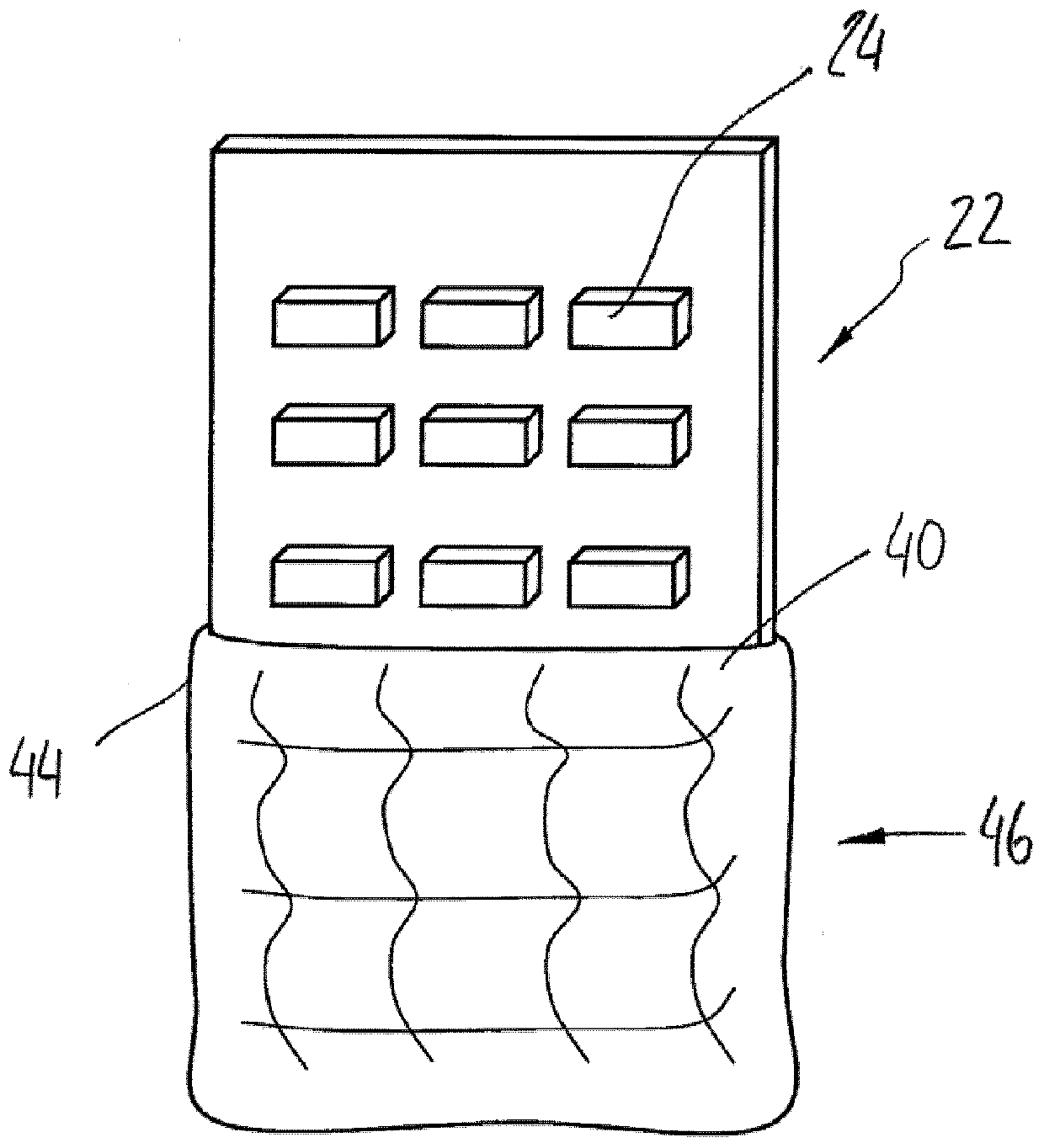
[0050] Figure 1b An insulating layer 46 is shown disposed partially over the electronic component 22 . Electronic components 24 that operate, create or process potentials or voltages exceeding at least a first voltage threshold are covered by a solid insulating layer 40. The solid insulating layer 40 is provided by potting. The solid insulating layer 40 includes a substantially planar outer surface 44 and an inner surface. An inner surface of the solid insulating layer 40 is at least partially in contact with the electronic component 22 . The upper region of the electronic components 22 is not covered by the insulating layer 46 because the components disposed in this region do not operate, create, use or process voltages that exceed the first voltage threshold. In this case, an additional solid insulating layer is unnecessary. ...


PUM


Abstract

Power supply unit, in particular for a sterilization device, comprising at least one electric component, wherein, at least one of the electric components is at least partly covered with a solid insulation layer, wherein the solid insulation layer is adapted to provide an electric insulation.

Description

technical field [0001] The present invention relates to a power supply device, in particular to a power supply device for a sterilizing device; to a sterilizing device, in particular to a sterilizing device for packaging materials; and to an electronic component, in particular to a Voltage doubler for the power supply unit described above. Background technique [0002] Electron beam irradiation has been considered a promising alternative for sterilization purposes, for which wet chemistry involving hydrogen peroxide has been the traditional technology platform. E-beam irradiation provides sufficient sterilization for eg packaging materials, eliminating the negative effects of wet chemistry eg in packaging machines. In this context, a power supply unit is necessary to provide a high voltage for operating one or more electron beam emitters. However, generating high voltages involves problems such as creating coronas and arcs within the housing of the power supply unit. In p...

Claims


Application Information

Patent Timeline
Patent Type & Authority Patents(China)
IPC IPC(8): H05K7/20A61L2/08
CPCA61L2/087B65B55/08H05K7/20463H05K1/11H05K1/185H05K3/285H05K2201/10H05K2201/10151H05K2203/1377
Inventor 约瑟夫·伊兹赖利特
Owner TETRA LAVAL HLDG & FINANCE SA
Why Eureka
Try Eureka