Washing machine damping device

A shock absorption device and a washing machine technology, applied in the field of washing machines, can solve the problems of large damping force, small damping force, supply, etc., and achieve the effects of avoiding up and down movement, improving vibration and noise level, and improving shock absorption performance.

Inactive Publication Date: 2016-10-19
QINGDAO HAIER WASHING MASCH CO LTD
View PDF7 Cites 12 Cited by
  • Summary
  • Abstract
  • Description
  • Claims
  • Application Information

AI Technical Summary

Problems solved by technology

[0007] Although the above structure uses a group of series-connected springs to provide damping force, it does not solve the problem of providing a relatively large damping force to suppress the vibration of the internal system at the moment of dehydration, nor can it provide a small damping force during the dehydration stable stage. solve the real problem

Method used


Image

  • Washing machine damping device
  • Washing machine damping device
  • Washing machine damping device

Examples


Embodiment 1

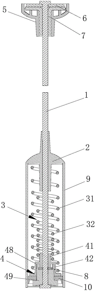
[0042] Such as figure 1As shown, two springs 31, 32 are arranged between the bracket 2 and the spring seat 4 described in this embodiment. The lengths of the two springs 31, 32 are different, and the lower ends are fixed with the spring seat 4. When the amplitude is small, the spring The distance between the seat 4 and the bracket 2 changes little, and only the longer spring 31 acts to produce less damping; when the amplitude is large, the distance between the spring seat 4 and the bracket 2 changes greatly , the shorter spring 32 is also compressed, and at this time, the two springs 31 and 32 both work to produce greater damping and suppress vibration.

Embodiment 2

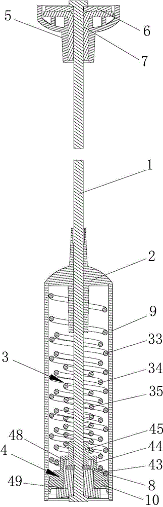
[0044] This embodiment makes a further improvement on the basis of Embodiment 1. The spring 32 with short length in the spring group 3 gradually increases in stiffness coefficient from top to bottom, and / or, the pitch of the spring 32 gradually decreases from top to bottom ( refer to figure 1 ), from top to bottom is the extending direction from one end of the bracket 2 to one end of the spring seat 4.

[0045] The change characteristic of the stiffness coefficient / pitch of the spring can slow down the change of the damping force, especially prevent the sudden increase of the damping force when the spring works.

Embodiment 3

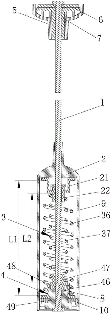
[0047] In this embodiment, a further improvement is made on the basis of the above-mentioned embodiments. There are two springs 31 and 32 with different lengths, and the longer spring 31 is arranged on the outer ring of the shorter spring 32 .

[0048] The upper end surface of the spring seat 4 connecting the springs 31, 32 gradually lowers from the center to the outer periphery to form a stepped boss structure. Such as figure 1 As shown, the lower end of the shorter spring 32 is sleeved on the outer periphery of the centermost boss 41 of the spring seat 4 , and the longer spring 31 is sleeved on the outer periphery of the lower boss 42 of the outer ring. The fixing structure can prevent the two springs from shaking and being entangled when the suspender is working, which affects the damping performance.

[0049] Alternatively, for two springs with different lengths, the shorter spring is arranged on the outer ring of the longer spring. The upper end surface of the spring se...


PUM


Abstract

The invention discloses a washing machine damping device, comprising a suspension rod, and a bracket, a spring set, and a spring seat installed on the lower end of the suspension rod from up to bottom in sequence. The spring set comprises at least two springs, and the springs embed in each other. One end of each spring in the spring set is fixed. The lengths of at least two springs in the spring set are different. The length of each spring in the spring set gradually increases from inside out. Rigidity coefficients of at least two springs in the spring set are different. The rigidity coefficient of each spring in the spring set gradually reduces from inside out. The rigidity coefficient of the spring whose length is shortest in the spring set gradually increases from top to bottom, and / or, the pitch of the spring whose length is shortest in the spring set gradually reduces from top to bottom. The device simultaneously realizes dual functions of transient dehydration vibration elimination and steady dehydration vibration isolation, so as to effectively improve vibration noise level in a dehydration stage. The device is characterized by variable damping vibration attenuation.

Description

technical field [0001] The invention relates to the field of washing machines, in particular to a shock absorbing device for washing machines. Background technique [0002] Existing washing machines are divided into pulsator washing machines and drum washing machines. The structure of the pulsator washing machine includes: a shell forming the appearance of the washing machine; an outer shell that is suspended and fixed by a supporting member and used to accommodate washing water is provided inside the shell; Barrel; rotatably installed inside the outer barrel and an inner barrel with an agitator at the bottom; a driving motor installed on the lower side of the outer barrel and used to generate the driving force of the agitator and the inner barrel; used to drive the driving force of the driving motor The power transmission device selectively provided to the agitator and the inner tub; the drainage device installed on the lower part of the outer tub and used to discharge the ...

Claims


Application Information

Patent Timeline
Patent Type & Authority Applications(China)
IPC IPC(8): D06F37/20
Inventor 许升吕艳芬今井俊次彭秀文
Owner QINGDAO HAIER WASHING MASCH CO LTD
Why Eureka
Try Eureka