Low-speed high-torque and permanent-magnet synchronous high-speed automatic tool-changing electric spindle

A permanent magnet synchronous, automatic tool change technology, applied in clamping, supporting, positioning devices, etc., can solve the problems of increased heat generation, shortened bearing service life, difficulty in high-speed operation, etc., to reduce damage, reduce rotor heating, and reduce high-speed Magnetic field weakening effect

Active Publication Date: 2016-10-26
江苏华雕机械有限公司
View PDF5 Cites 8 Cited by
  • Summary
  • Abstract
  • Description
  • Claims
  • Application Information

AI Technical Summary

Problems solved by technology

In recent years, with the market's demand for low-speed and high-torque electric spindles, an electric spindle that uses permanent magnet synchronization as a built-in motor combined with automatic tool change has emerged, but because the rotor design is derived from ordinary synchronous motors, the high-speed electromagnetic is weakened. It is obviously prominent, and the heat is greatly increased. In addition, the use of surface-mounted permanent magnet processing technology makes high-speed operation more difficult; in addition, when the traditional automatic tool-changing electric spindle is changing the tool, the axial force of the tool change all acts on the high-speed precision grinding bearing. Significantly shortens the service life of the bearing

Method used


Image

  • Low-speed high-torque and permanent-magnet synchronous high-speed automatic tool-changing electric spindle
  • Low-speed high-torque and permanent-magnet synchronous high-speed automatic tool-changing electric spindle
  • Low-speed high-torque and permanent-magnet synchronous high-speed automatic tool-changing electric spindle

Examples


Embodiment Construction

[0044] The technical solutions in the present invention will be clearly and completely described below in conjunction with the accompanying drawings in the embodiments of the present invention. The following examples are only used to illustrate the technical solution of the present invention more clearly, but not to limit the protection scope of the present invention.

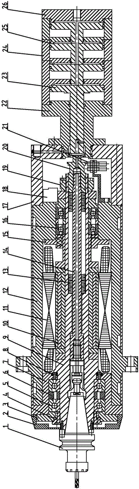
[0045] see Figure 1 to Figure 5, is a low-speed high-torque permanent magnet synchronous high-speed automatic tool-changing electric spindle, the main structure includes: a body 12, a stator 11, a rotor 10, a rotor shaft 9, a spring preload mechanism 15, and a front bearing 5 are arranged inside the body 12 And the rear bearing 16, wherein, the front bearing 5 and the rear bearing 16 are respectively arranged at the two ends of the rotor shaft 9 and the front bearing 5 is installed on the front end cover 7 of the body, the front bearing 5 and the rear bearing 16 all adopt two groups of paired parallel bearings...


PUM


Abstract

The invention discloses a low-speed high-torque and permanent-magnet synchronous high-speed automatic tool-changing electric spindle. The electric spindle comprises a motor body, and a stator, a rotor, a rotor shaft, a spring pre-tightening mechanism, a front bearing and a rear bearing are arranged inside the motor body. The electric spindle further comprises a connection base fixed to the rear end of the motor body, a connector fixedly connected to the connection base, a steam cylinder assembly fixedly connected to the connector, a rear cover arranged at the end of the steam cylinder assembly and a front end cover connected to the front end of the motor body. A tool loosening and pulling mechanism is arranged in the center of the rotor shaft, a pulling claw is arranged at the front end of the tool loosening and pulling mechanism, a disc spring assembly is installed in the middle of the tool loosening and pulling mechanism, a high-performance sensor is adopted together, and therefore automatic tool changing is more convenient and accurate and rapider. A magneto-electric coder is adopted at the rear end, so that low-speed torque output is more balanced. Compressed air is adopted for non-contact air sealing so that higher rotation speed can be obtained. The electric spindle is simple and compact in structure and powerful in function, is smaller than common electric spindles with the same power in size, has the advantages that the speed is low and the torque is high and can be widely applied to high-speed and low-speed precision machining of various materials.

Description

technical field [0001] The invention belongs to the technical field of mechanical and electrical integration engineering, and in particular relates to a low-speed, high-torque permanent magnet synchronous high-speed automatic tool-changing electric spindle. Background technique [0002] The commonly used automatic tool change electric spindle is a high-speed asynchronous motor built in the spindle, plus a set of cylinder and loose broach mechanism, so as to realize the high speed, high precision and high efficiency of the mechatronic power components, mainly used in high-speed machining The machine tool realizes high-speed processing of different materials and improves processing efficiency. [0003] At present, high-speed electric spindles with automatic tool change are relatively common in the market, but there are few electric spindles that can run at high speed or low speed and have high torque output. The main reason is that traditional automatic tool change electric sp...

Claims


Application Information

Patent Timeline
Patent Type & Authority Applications(China)
IPC IPC(8): B23B19/02B23Q3/155B23Q11/12
CPCB23Q3/155B23Q11/127
Inventor 翟海华翟会兴
Owner 江苏华雕机械有限公司
Why Eureka
Try Eureka