

Mechanical stress arm
A robotic arm and round rod technology, applied in the field of dicing saw equipment, can solve the problems of small objects falling into small places, electromagnetic induction interference, difficult to take out by hand, etc., saving manpower and material resources, and working accuracy. High, time-saving effect
- Summary
- Abstract
- Description
- Claims
- Application Information
AI Technical Summary
Problems solved by technology
Method used
Image

Examples
Embodiment Construction
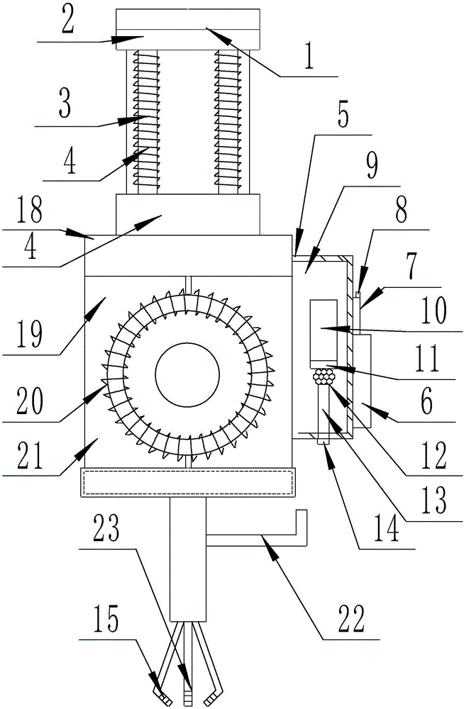
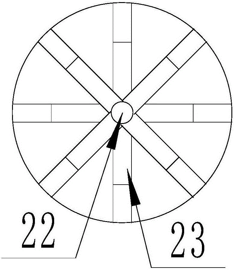
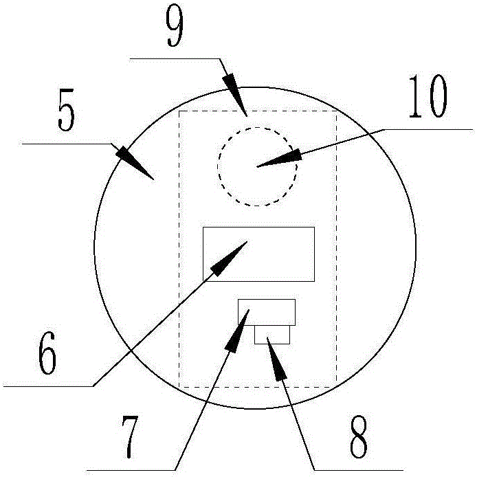
[0015] The present invention is specifically described below in conjunction with accompanying drawing, as Figure 1-3 As shown, a force-bearing mechanical arm includes a round rod (1), a telescopic rod (2) is provided on one side of the round rod (1), and a magnetic effect coil A (3) is wound on the round rod (1). ), the magnetic effect coil A (3) is nested with a ring A (4), and the ring A (4) is provided with a circular housing (5), and the circular housing (5) The upper surface is provided with a dual-control function touch switch system. The dual-control function touch switch system is provided with a mutual control touch sensor button (6) on the upper surface of the circular shell (5), and a mutual control touch sensor button (6). (6) the backlight indicator light (7) at the lower end, the sound processor (8) that is arranged on the left side of the backlight indicator light (7), the PCB circuit board (9) that is arranged in the circular casing (5), is arranged on The in...
PUM
 Abstract
Description
Claims
Application Information