Electric-hydraulic composite braking system for electric automobile and optimization method of electric-hydraulic composite braking system

A technology for electric vehicles and braking systems, applied in electric braking systems, electric vehicles, brakes, etc., can solve problems such as limiting the effect of braking energy recovery, driver braking stability, and driver inconsistent braking feeling.

Inactive Publication Date: 2016-10-26
NANJING UNIV OF AERONAUTICS & ASTRONAUTICS
View PDF5 Cites 20 Cited by
  • Summary
  • Abstract
  • Description
  • Claims
  • Application Information

AI Technical Summary

Problems solved by technology

In the actual braking conditions of electric vehicle compound braking, on the one hand, under the same brake pedal angle, due to the different dynamic characteristics of regenerative braking and hydraulic friction braking output, the driver often has different braking modes. inconsistent brake feel
On the other hand, even in the same braking mode, the braking force response characteristics due to different braking force distribution ratios are also different, which will cause the driver to ...

Method used


Image

  • Electric-hydraulic composite braking system for electric automobile and optimization method of electric-hydraulic composite braking system
  • Electric-hydraulic composite braking system for electric automobile and optimization method of electric-hydraulic composite braking system
  • Electric-hydraulic composite braking system for electric automobile and optimization method of electric-hydraulic composite braking system

Examples


Embodiment Construction

[0055] Below in conjunction with accompanying drawing, technical scheme of the present invention is described in further detail:

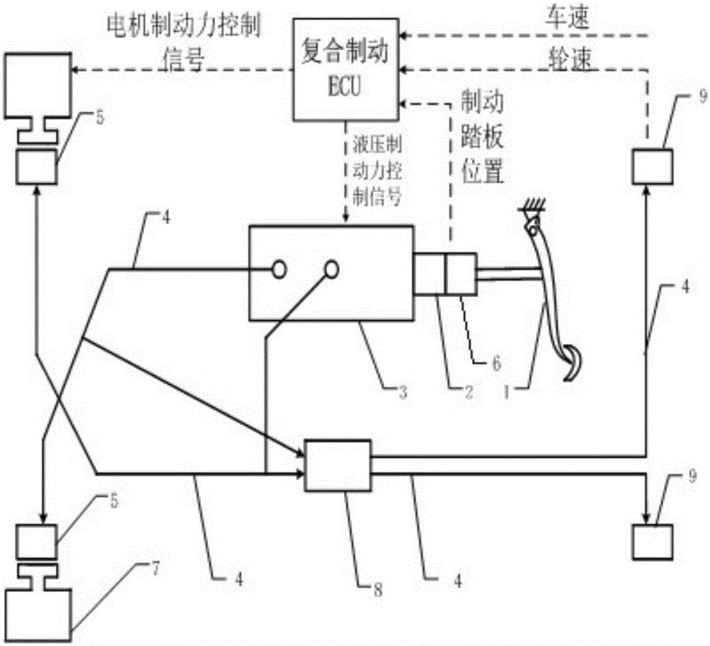
[0056] Such as figure 1 As shown, the present invention discloses an electro-hydraulic composite braking system for an electric vehicle, which includes a motor regenerative braking force module, a hydraulic braking force module and a composite braking force control module;

[0057] The motor regenerative braking force module includes two hub motors, a brake pedal position sensor, four wheel speed sensors, a vehicle speed sensor, a super capacitor, a two-quadrant DC-DC converter and a first ECU;

[0058] The two in-wheel motors are correspondingly arranged in the two front wheels of the electric vehicle for driving and braking the two front wheels;

[0059] The brake pedal position sensor is arranged at the brake pedal, and is used to obtain the stroke of the brake pedal when the brake pedal is stepped on;

[0060] The four wheel speed sensors are...


PUM


Abstract

The invention discloses an electric-hydraulic composite braking system for an electric automobile and an optimization method of the electric-hydraulic composite braking system. The electric-hydraulic composite braking system for the electric automobile comprises a motor regeneration braking force module, a hydraulic braking force module and a composite braking force control module. The motor regeneration braking force module comprises two hub motors, a brake pedal position sensor, four wheel speed sensors, an automobile speed sensor, a super-capacitor, a two-quadrant DC-DC converter and a first ECU. The hydraulic braking force module comprises an oil pump motor, a hydraulic oil pump and a second ECU. In the traveling process of the automobile, through detection of the automobile speed and the wheel speed of automobile traveling and brake pedal position signals, the composite braking force control module controls the distribution ratio between the motor regeneration braking force module and the hydraulic braking force module. Meanwhile, through multi-objective optimization conducted on the electric-hydraulic composite braking system, the braking pedal feeling and motor recovered energy serve as objects, and under the ECE laws and regulations, the relatively high energy recovery rate and the proper brake pedal feeling are obtained.

Description

technical field [0001] The invention relates to the field of electro-hydraulic composite braking systems for electric vehicles, in particular to an electro-hydraulic composite braking system based on electric vehicles and an optimization method thereof. Background technique [0002] Compared with the traditional hydraulic braking system, the electro-hydraulic composite braking system has the advantages of good braking stability and a certain energy recovery rate. Since the system can recover part of the braking energy during the braking process, it can When braking, the ECU can increase the ratio of the regenerative braking force of the motor to increase the energy recovery rate. On the contrary, during high-intensity braking, the braking force can be completely provided by hydraulic braking force to ensure braking efficiency. [0003] However, in the existing research on the electro-hydraulic hybrid braking system of electric vehicles, there is still very little research o...

Claims


Application Information

Patent Timeline
IPC IPC(8): B60T8/17B60T13/12B60T13/66B60L7/10
CPCB60L7/10B60T8/17B60T13/12B60T13/66
Inventor 王春燕李文魁赵万忠
Owner NANJING UNIV OF AERONAUTICS & ASTRONAUTICS
Why Eureka
Try Eureka