Staggering discharging device of adjusting box

A technology of discharging device and adjusting box is applied in the field of dislocation discharging device of adjusting box and discharging device of adjusting box of infusion set, which can solve the problems of increasing raw materials for manufacturers, production cost, large volume of feeding device and complicated structure, etc. , to achieve the effect of saving raw materials and production costs, smooth operation, and accurate positioning

Pending Publication Date: 2016-10-26
梁启明
View PDF1 Cites 6 Cited by
  • Summary
  • Abstract
  • Description
  • Claims
  • Application Information

AI Technical Summary

Problems solved by technology

[0003] Chinese Invention Patent No. ZL201410143384.2 discloses the structure of "a feeding device for a medical device assembly machine"; it includes a feeder groove for conveying materials, a suction nozzle for sucking materials and fixing the materials in the positioning holes The suction positioning structure and other components, its main feature is that the channel groove, suction nozzle and suction positioning structure are all 18 stations, that is, there are 18 material channel grooves, 18 suction nozzles and 18 suction positioning The structure enables the feeding device to have the ability of batch feeding and improves the feeding efficiency; its disadvantage is: because the feeder groove, the suction nozzle and the suction positioning structure are all 18 stations, resulting in other parts that cooperate with these parts Components also need 18 stations (including the discharge device of the adjustment box also requires 18 stations), so as to ensure the feeding efficiency of the equipment, which will lead to larger parts such as the feeding device, the discharge device, etc. As a result, the volume of the feeding device is larger, the structure becomes more complicated, and the raw material and production costs of the manufacturer are increased.
At present, there is no research on a small volume, many stations, and a high-precision feeding device and discharging device.

Method used


Image

  • Staggering discharging device of adjusting box
  • Staggering discharging device of adjusting box
  • Staggering discharging device of adjusting box

Examples


Embodiment

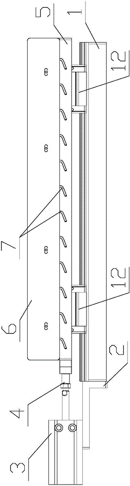
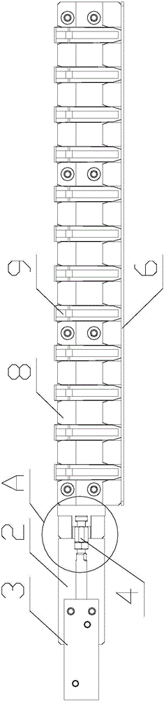
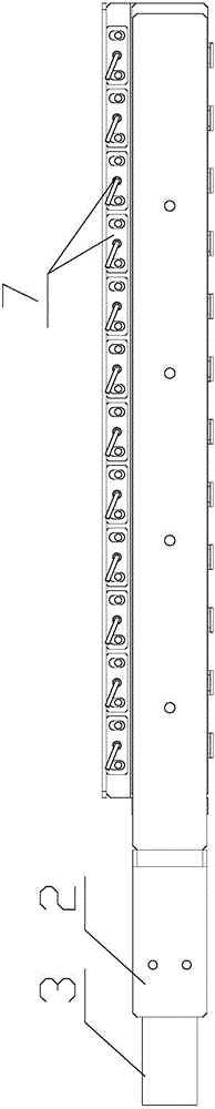
[0037] Embodiment: a kind of adjustment box misalignment discharging device, such as Figure 1~6 As shown, the guide rail installation plate 1 is included, the guide rail installation plate 1 is cuboid, the cylinder 3 installation plate 2 is fixed on the guide rail installation plate 1, and the cylinder 3 installation plate 2 is fixed on one of the end faces of the guide rail installation plate 1 with the smallest area. The cylinder 3 mounting plate 2 is L-shaped, the width of the cylinder 3 mounting plate 2 is consistent with the guide rail mounting plate 1, the shorter side of the cylinder 3 mounting plate 2 is fixed with the cylinder 3 mounting plate 2, and the cylinder 3 mounting plate 2 is installed for The height of the horizontal plane where the cylinder 3 is installed is higher than the height of the horizontal plane for installing the linear guide rail 10 on the guide rail mounting plate 1; as figure 1 As shown, a cylinder 3 is fixed on the mounting plate 2 of the cyl...


PUM


Abstract

An adjustment box dislocation discharge device, including a guide rail installation plate, the guide rail installation plate is in the shape of a cuboid, a cylinder installation plate is fixed on the guide rail installation plate, and the cylinder installation plate is fixed on one of the end faces of the guide rail installation plate with the smallest area. The plate is L-shaped, the width of the cylinder mounting plate is the same as that of the guide rail mounting plate, and the shorter side of the cylinder mounting plate is fixed with the cylinder mounting plate. The height of the horizontal plane where the linear guide rail is installed; the cylinder is fixed on the cylinder mounting plate, and the cylinder is fixed horizontally on the cylinder mounting plate; the cylinder rod is fixed on the cylinder, and the cylinder rod is set towards the direction of the cylinder mounting plate, and one end of the cylinder rod is provided with threads. The thread on the cylinder rod is connected with the transition device through a nut, and the transition device is slidably connected with the mounting plate of the positioning groove.

Description

technical field [0001] The invention belongs to the technical field of medical device manufacturing, and relates to a discharge device for an adjustment box of an infusion set, in particular to a discharge device for a dislocation adjustment box. Background technique [0002] The infusion set is an auxiliary device commonly used in medical treatment. It is mainly used for intravenous infusion. It is an important disposable medical consumable that has undergone aseptic treatment and establishes a channel between the vein and the liquid medicine; it is generally composed of an intravenous needle, a protective cap, The liquid medicine filter, the regulator used to control the flow rate of the liquid medicine, the dripping pot, the cork piercer, and the air filter of the intake pipe are connected; all parts are connected by conduits, and the liquid medicine circulates through the conduits; the regulator can be used for different Time, different personnel adjust different liquid ...

Claims


Application Information

Patent Timeline
Patent Type & Authority Applications(China)
IPC IPC(8): B65G47/82B65G43/08
CPCB65G47/82B65G43/08B65G2201/0214B65G2203/042
Inventor 梁启明
Owner 梁启明
Why Eureka
Try Eureka